Continue to Site

Welcome to our site!

Electro Tech is an online community (with over 170,000 members) who enjoy talking about and building electronic circuits, projects and gadgets. To participate you need to register. Registration is free. Click here to register now.

  • Welcome to our site! Electro Tech is an online community (with over 170,000 members) who enjoy talking about and building electronic circuits, projects and gadgets. To participate you need to register. Registration is free. Click here to register now.

Engine Temperature using an AD590 on the Oil Pressure Wire to the engine

Status
Not open for further replies.
but the bridge, OP-AMP and display unit are all in the engine compartment with the AD590 and the pressure switch.
No, the display and op amp electronics are in the passenger compartment.
The AD590 (and pressure switch of course) are in the engine compartment.
 
No, the display and op amp electronics are in the passenger compartment.
The AD590 (and pressure switch of course) are in the engine compartment.
Yes I see that now, but the way the circuit was drawn, it was not obvious (to me).

JimB
 
But you need a stable voltage to generate the output signal offset the TS desires.
Why?

A given current through a known resistor will produce a specific signal voltage. As long as that stays within the common mode range of a differential amplifier it can be changed to zero referenced or shifted to any required bias offset, for whatever display module is in use.

The differential amp and onward can run on a stabilised supply - but the sensor does not need regulation.
 
But my opinion is "just run a second wire".
I assume the TS has a good reason for not wanting to do that.

And I don't see that running a second wire would significantly simplify my post #2 circuit (which I don't consider "convoluted"), expect for the elimination of the MOSFET driving the Oil Light.
 
Last edited:
Why?
A given current through a known resistor will produce a specific signal voltage. As long as that stays within the common mode range of a differential amplifier it can be changed to zero referenced or shifted to any required bias offset, for whatever display module is in use.
The differential amp and onward can run on a stabilised supply - but the sensor does not need regulation.
"Why?"
How do you get a stabile bias offset without a stable voltage?
If you have a way to do that please show how.
 
Last edited:
How do you get a stabile bias offset without a stable voltage?
What "stable bias offset"??

The temperature transducer IC is it's own current regulator, near regardless of voltage within it's working range.
A variation of a couple of volts will only affect the reading by something like +/- half a degree; irrelevant for this application.

The only point that needs a stable offset is after the differential amp, which is part of the in-vehicle electronics and can be fully regulated.
 
Actually when this all started a wheatstone is the only way I could remember on how to do offset something. I do see now how it needs to go hand in hand with supply regulation.
"crutschow" I do really like your circuit and will certainly give it a shot as it more effectively can regulate the supply at 5 volts without worrying about regulator dropout specifications Quite Brilliant! Also adding a "MOSFET" for the indicator lamp is great will be easy and I think is probably going to make my temperature readings a little better behaved.
Sure "JimB" you're right about adding a wire however wanted to come up with something that didn't need that done for my Classic Car.

"rjenkinsgb" Not sure I'm up on just how to offset the op amp between stages or at the display adjustments for the 255' Kelvin to Zero Degrees Fahrenheit. I guess that is all handled in the "crutschow" Spice. I have a schematic somewhere of how we did it at HP back in the 80's but will have to find it. Thanks. Everyone. I will post when I have something going.
 
Last edited:
What "stable bias offset"??
The offset to give 0V output when the sensor temperature is 0°F (255µA).
The only point that needs a stable offset is after the differential amp, which is part of the in-vehicle electronics and can be fully regulated.
No, it's not part of the vehicle electronics, it's an added display circuit.
It's a classic car with a 6V battery and likely little vehicle electronics beyond a possible tube-powered radio.

I understand that the sensor itself doesn't need a regulated voltage (read my previous posts), so if you agree that the circuit needs a regulated voltage, why are you quibbling about exactly where?
 
Last edited:
I do really like your circuit and will certainly give it a shot as it more effectively can regulate the supply at 5 volts without worrying about regulator dropout specifications
I'm actually regulating to 6V (REF voltage) from the battery 6.3V (about 7.2V with the engine running).
Not sure I'm up on just how to offset the op amp between stages or at the display adjustments for the 255' Kelvin to Zero Degrees Fahrenheit. I guess that is all handled in the "@crutschow" Spice.
Resistor R2 in my schematic serves that function by cancelling out the 255µA current at 0°F.

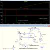
Below is the latest circuit with R5 changed to a standard 1% resistor value:

1610990838155.png
 
Last edited:
No, it's not part of the vehicle electronics, it's an added display circuit.
It's a classic car with a 6V battery and likely little vehicle electronics beyond a possible tube-powered radio.
"In vehicle", as in being part of the digital display unit, rather than part of the oil pressure switch circuit.

This is a back-of-a-beermat grade version of what I'm getting at; not bothering showing the ignition switch, opamp supply etc.

Minimal mods to the original oil pressure switch circuit, with the switch still directly operating the lamp; KISS design.

The diode and resistor are added in series, and the voltage across the resistor measured with a differential amp.
The 'K offset is via a preset with a stabilised voltage; either to the reference of the differential amp as show, or better still if the voltmeter module has a differential input connect the negative of that to the preset and ground the diff amp ref.

That would avoid the need for a fancier rail to rail opamp and allows temperatures below 0'C to be shown.

oil-temp.png
 
This is a back-of-a-beermat grade version of what I'm getting at;
You may need to have another beer and look at the front. ;)
The adjustment gives only a positive output offset, whereas it needs a negative offset to cancel the 255µA sensor current at 0 degrees F and give a 0V output.

Also the equivalent resistance of RP1 will unbalance the differential common-mode rejection of the op amp, leading to a change in output with a change in battery voltage.
Even with R3 connected to ground and 1% resistors for R2 through R5, a 1 volt change in the battery voltage could cause a 10 mV (10 degree F) change in the output voltage.
 
Last edited:
You may need to have another beer and look at the front.
It's a concept, not an exact circuit.

I did say it would be better with a differential input display and with the bias pot connected to the negative input of that instead.
What's wrong with that?

It's something appropriate for purpose, not a process control system that needs to be accurate to fractions of a percent.
 
I haven't been able to locate the AD590 Probe somewhere in my Junk or the Schematic but Here is a Photo showing the HP Transducer Interface Boards we used often as far as 1000' or more away from HP data acquisition volt meters and power supplies. This Schematic is just from what I remember about the boards. We had 3 types all -10 to + 10 Volts output (Type 1 -100'F to +100'F), (Type 2 Zero F to 200'F) and Type 3 a current interface board that worked off of a CT mounted in 480V load centers. The Type 3 boards were sometimes used for other interfaces such as the AD590 Temperature Probe, pH, water ppm, wind speed, Gas detectors, RH, or HVAC or something.
HP Transducer Boards.jpeg
 
Please don't take the above schematic as anything thing at all near right, I have been tracing the board out and will post the correct schematic. For one thing there are only 2 zener diodes, just on the Negative that run the Temperature IC and reference the OP amps. Also I have the input stages switched around above. The OP amp is powered directly from the +15 & -15 Supplies.
 
Here is a Photo showing the HP Transducer Interface Boards we used often
Are you considering using something like that for your car temperature circuit?
 
I could just use one of these but would need to run a 6 to 31 volt dc boost circuit to power it which I also have but I would prefer a simpler design.
It might work however gain and offset would have to be recalculated to make it operated between 0-2.4Volts output and a IR dropping resistor added to use with the AD590. . Maybe you guys would know how to calculate the resistor values needed.
If I can find the AD590 Probe I will try it on the bench. When I used to calibrate these they have a Common Mode signal rejection that has to be set for Zero 1st then I would put a batch of them 25 boards or 50 boards into a invironmental test chamber at Zero F to adjust the offset then gain at 100' F then adjust the offset again after installation.
But really the more. simple Ideas we are working with here would be fine. I am most concerned with Engine Temperatures from 180-240'F Although it's always nice to see the cold start temperature.

My Latest Board Trace Out Schematic for the LM358 Transducer Op Amp Circuit Board:

LM358_Transducer_Board_SCH.jpeg
 
Last edited:
Status
Not open for further replies.

New Articles From Microcontroller Tips

Back
Top