Continue to Site

Welcome to our site!

Electro Tech is an online community (with over 170,000 members) who enjoy talking about and building electronic circuits, projects and gadgets. To participate you need to register. Registration is free. Click here to register now.

  • Welcome to our site! Electro Tech is an online community (with over 170,000 members) who enjoy talking about and building electronic circuits, projects and gadgets. To participate you need to register. Registration is free. Click here to register now.

ETO Online Quiz Sheets.

Status
Not open for further replies.
Hmm, I just realized that some of the questions are swapped around. Q4 is all the way down where Q10 should be, and Q10 is where Q4 should be...

So are you referring to Q10 then?

Q4 and Q10 were swapped over in order to place the image question as the last question, thats all.
 
Q4 and Q10 were swapped over in order to place the image question as the last question, thats all.

Ah, ok. was wondering about that. Thanks Eric :)
 
I still need a required voltage for Q4. Or, if I don't then someone please explain.

Mike.
 
I still need a required voltage for Q4. Or, if I don't then someone please explain.

Mike.

It's an ohm's law problem. You are told that the voltage across the two series resistors is 8 volts, and you are given the total current through the resistors. Using that, you can find the total resistance of the circuit, and go from there.

Regards
 
It's an ohm's law problem. You are told that the voltage across the two series resistors is 8 volts, and you are given the total current through the resistors. Using that, you can find the total resistance of the circuit, and go from there.

Regards

hi,
I had failed to swap the Answer boxes for 4 and 10.!! duh!!:eek:

Try it now.

Mike,
Open another cannie, you're OK.:D
 
Last edited:
This is a poorly presented post, would you care to explain in terms the rest of us can understand what you are trying to say.??

How much of my posting were you able to understand?
 
Eric, I believe Colin means that there are some text within the images that are highlighted blue when they look as though they should be in black

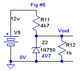
q8img6.gif


See the 4v7
 
Last edited:
hi EM,
The voltages in Blue near the Zener's indicate the Zener voltage, I did this so the user would not have to lookup the zener datasheet.

I honestly do not believe its necessary to make any changes to the images based on what Colin has to say, he knows perfectly well what the drawings represent.

E.
 
Last edited:
If you can't see the problem, I am wasting my time.

You're not exactly making your question clear. If you can't clarify your problem, then you're wasting my time.

Why is it a problem if the zener voltage is the same color as vout? The zener label is way over by the diode, not near vout. How is it confusing?
 
Last edited:
Eric,


Here is the corrected drawing for Q9 of Quiz 7. I made a slight error in the drawing so here is the corrected version. Thanks.


Trivia note:
Anyone pronounce "Euler's" as either:
"you-lers"
or as "eee you-lers"
or as "oil-ers" ?
 
Last edited:
Quizz V7.0 by Mr Al (Electronic and Electrical). Score = 7

Here's what I got wrong:

Q2 (Transformers), Q6 (LCD) and Q10.

It was a nice test. Just per curiosity, for the question on State Space. Would you go for Laplace and find the inverse matrix of (p-IA) + Discretization (sampling of 1ms to find F and H), then Commandability matrix Wc and find the Command Vector Uc . Or did you just calculate it from the equation of a charging capacitor and replaced t with 10 ms ? (Knowing that if you do that, you'll find 95.162e-3).

Doing that with matrix calculations isn't worth it for a first order system in my opinion, so I guess you did it another way that's better and faster.

Thanks,
 
Last edited:
hi,
A simple True/False Quiz, in the Tools section.

Quiz V11.0 Mid Range 16F PIC's Timer0, Beginner Level
 
Last edited:
Status
Not open for further replies.

Latest threads

New Articles From Microcontroller Tips

Back
Top