Continue to Site

Welcome to our site!

Electro Tech is an online community (with over 170,000 members) who enjoy talking about and building electronic circuits, projects and gadgets. To participate you need to register. Registration is free. Click here to register now.

  • Welcome to our site! Electro Tech is an online community (with over 170,000 members) who enjoy talking about and building electronic circuits, projects and gadgets. To participate you need to register. Registration is free. Click here to register now.

Ferrite Bead

Status
Not open for further replies.
permeability with more conductive metallic oxide, makes them lossy
- good for BJT spurious resonance and EMI control in switches and logic and DC motor & stepper motor noise
- not good for RADAR pulses, MOSFET PWM bridges and high speed switches where latency is important

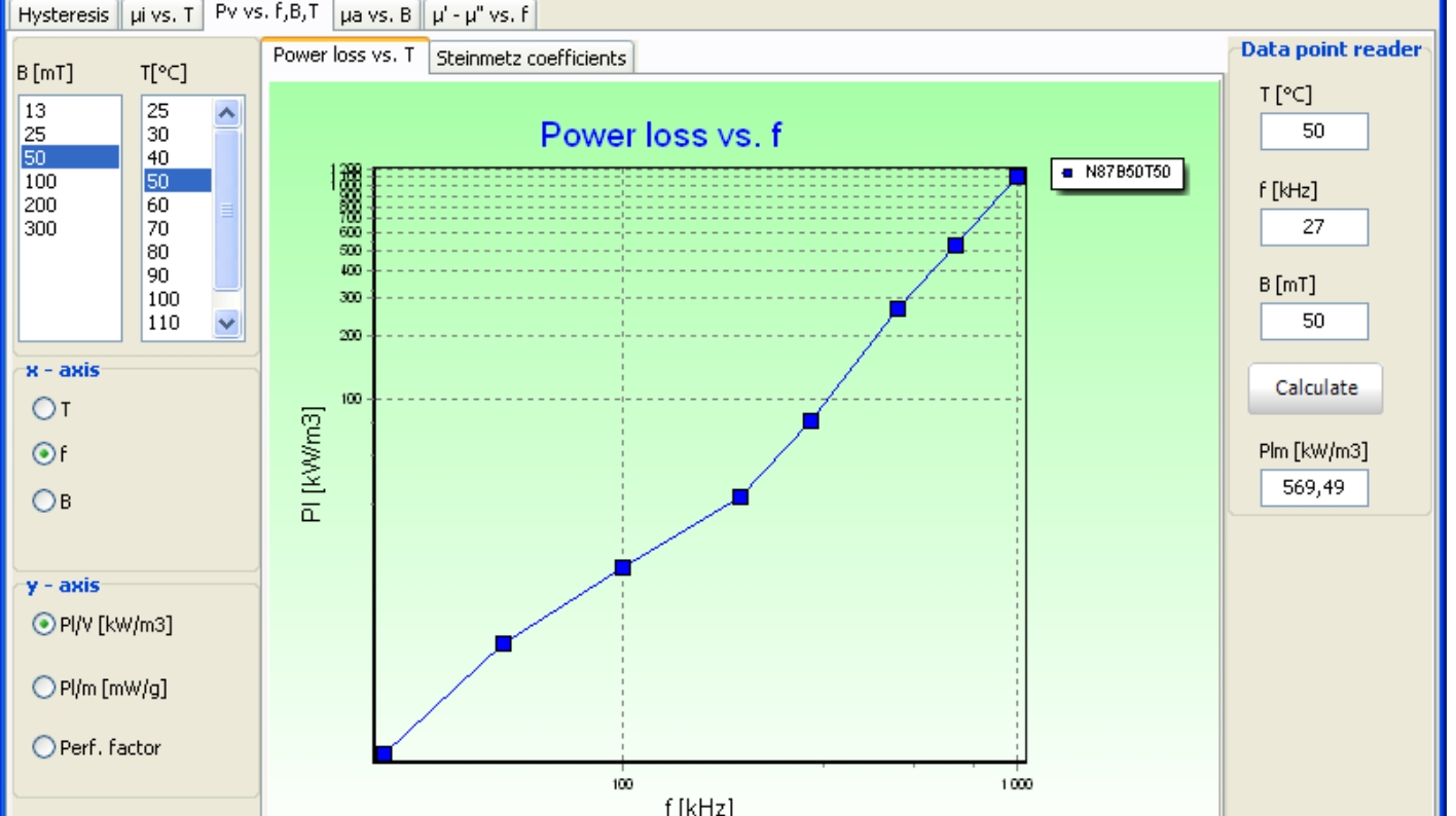
Some theory https://product.tdk.com/en/catalog/datasheets/ferrite_summary_en.pdf

Mn-Zn for high Mu low f EMI
Ni-Zn for lower Mu UHF/uWave

One of the best in Ferrite is TDK who have a design tool
https://en.tdk.eu/tdk-en/180490/design-support/design-tools/ferrites/ferrite-magnetic-design-tool
7695965300_1425670985.jpg


Catalog shows more than most makers of ferrite, but they make more for customers.
**broken link removed**
 
Last edited:
Tony, you missed the point. Nothing around the gate of a FET is happening at much over 1Mhz.

Hi there Mike,

That cant be true. Think about this, if we have a 100kHz converter, 1MHz would have a time period only 1/10 (one tenth) of the total switching period. If that were true, the MOSFET would be turning on and off very slowly compared to what we usually want to go for (tens of nanoseconds). Also, chip gate drivers are very very fast devices.

MOSFETs are slowed down sometimes for various reasons. One reason is the inductance in the source lead which leads to oscillations (due to unwanted degenerative source feedback) unless the MOSFET switches a tiny bit slower (slower than that tiny inductance can react to significantly). Another reason is to lower the inductive kick back when driving something like a transformer, but at the cost of lower efficiency. Another reason is lower EMI radiation.

When i worked in the industry we used low value resistors to handle all these problems, as they are more predictable. For super high efficiency (better than 90 percent) this may not be an option as it may eat up more power, power we dont want to waste. Ferrite beads have various different properties so i would not trust a new part...the only way would be in a tried and proven design with a given part number being used.
If the inductance is enough to slow the MOSFET just a little, then it could solve all those problems above and not eat up as much power doing so. We never did it that way though.
 
I said in previous post Ferrite is not good for RADAR ( meaning not good when you want good Radar resolution,)

But I had to laff when I read it again and remembered before I started at Burroughs Peripherals Division in early 80's they had a problem with 14" disk drives getting interference and data corruption in the tallest financial bldg. downtown.

They found out it was the 1kW RADAR pulse from Winnipeg Int'l Airport beaming every second and occasionally have collisions with read data.


The fix was better braid wire around the balanced differential signal cable and ferrite choke around it.
 
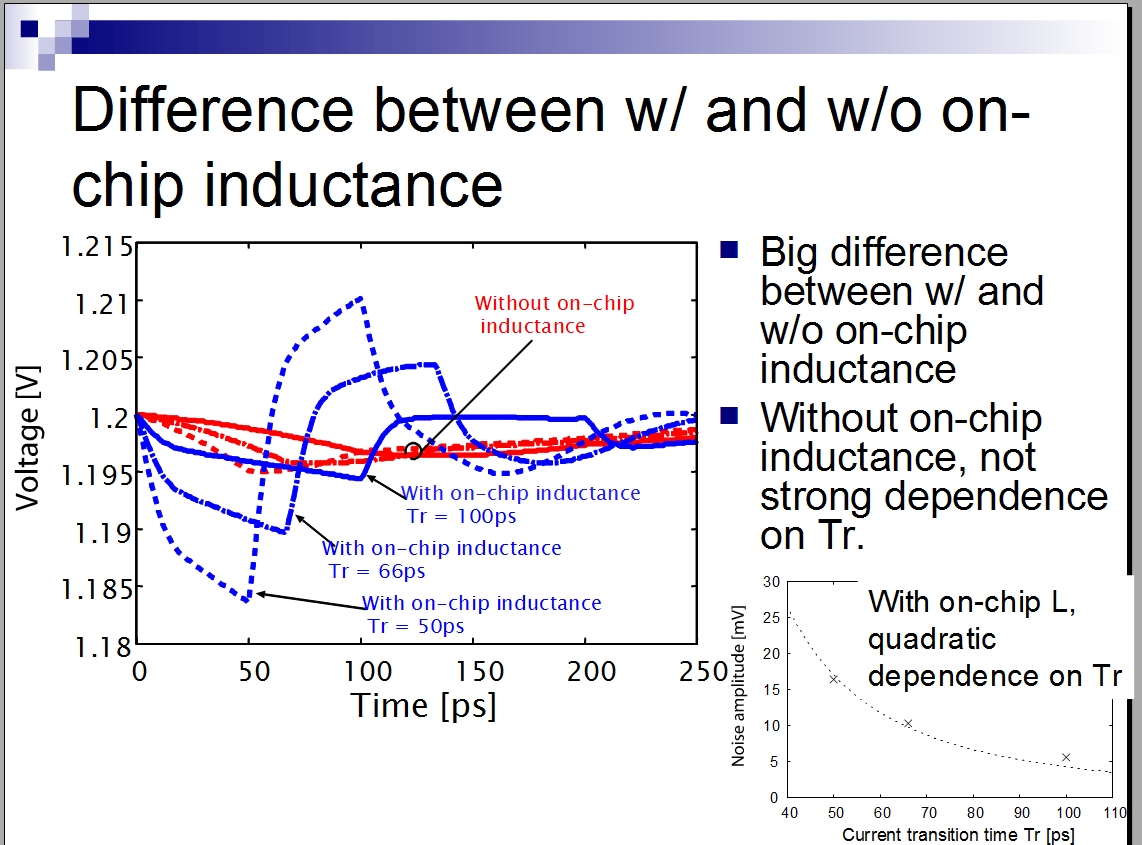
To add some perspective, IC design must consider ESL or effective series inductance in routing of high speed signals to reduce overshoot and ringing.

6353797400_1425672920.jpg
 
Tony, what does all the IGBT stuff have to do with Kinarfi's power Mosfet?
 
At the suggestion of MrAl, the nut with 10 turns of wire:
Steel Nut 10Turns.jpg

JimB
 
For the purposes of suppression of ringing and VHF parasitics, I would presume that the 10 ohm resistor would provide the majority of effect. This might also reduce resonant/ringing if whatever is driving it (say, a transformer) has the tendency to do so when terminated with a highly capacitively reactively load such as the gate of a FET. A lot of series resistance would imply that one needs not have a particularly fast rise time - such as on a switching converter.

About a year ago I had the (dis)pleasure and puzzlement of experiencing instability on a linear supply that several paralleled FETs as the active element of a series high-compliance current sink. The "giveaway" was that the voltage versus position of the setting for maximum current was inconsistent - plus the fact that the 100 MHz 'scope showed some "fuzz".

After cranking the sweep rate of the 'scope all of the way up - and then grabbing a frequency counter and holding it near the FETs - I was surprised to observe that these chunky FETs, with many 10's of nF of gate capacitance, were oscillating between 100 and 150 MHz. Having identified that, a whack on the forehead and a little bit of series resistance in each of their gate leads - 100 ohms or so, as that value was at hand - completely tamed the problem.

To be sure, I should have known better to omit the resistors in indvidual the gate leads (previously there had been one for all of the FETs) but I would have not guessed that plain, ordinary, cheap N-channel power FETs would have done anything at that frequency, let alone burn up 10's of watts!

Considering the feedback path (high intrinsic capacitance between FETs' terminals) coupled with the heavy, low inductance board traces and the parasitic reactances of the FETs themselves, I can kind of see what was happening and that just a few ohms of extra impedance of any kind on the gate lead may have quashed the problem before it began by removing that route of low-impedance coupling. I could also envision on a switching supply a similar thing happening with the rather high capacitances of driving/output windings parasitically coupling things together that one wouldn't otherwise think were "coupled" leading to untoward signal paths as well.

On a very simple circuit with a single FET, the one caveat that comes to mind in directly driving a FET is that some (e.g. op amps, some microcontrollers) do not like highly capacitive loads and a series resistor is indicated. A similar warning could conceivably be given where the FET's load could somehow be reflected back into the gate itself (e.g. Miller/gate-drain/gate-source capacitance and/or a protective device on the gate) and mess up the driving circuitry - but that is less likely to happen.
 
Tony, what does all the IGBT stuff have to do with Kinarfi's power Mosfet?
Everything is relevant that I contributed as his question was not specific to a design , a part number or an application.

The effect of large gate and drain pulse currents dI/dt is to cause EMI noise with crosstalk.
It gets worse when the load is inductive and far away from driver.
Adding a ferrite bead may reduce dI/dt but degrade dead band timing in bridges and worse... raise CM noise levels to cause false triggering in other circuits.

Often an isolated Gate drive is the best solution driven by low impedance source to a pulse transformer which can be much faster than optoisolators in small scale.

read here.
https://www.analog.com/library/analogDialogue/archives/46-11/gate_driver.html

In critical aspect to full-bridge high speed design is layout of common mode hgh currents so that it does not induce conducted noise seen as supply or return spikes. A dampened RC approach works in low-current designs, but as conductive and reactive path loss becomes significant with high current, the designer must give careful attention to transition speed and balanced gate drivers, output drivers and power & return paths with control asymmetric slew rates for turn on/off. Avalanche diodes are provided to assist in selected designs.
 
Last edited:
New Steering H Bridge 4.png Thanks for all the information, and here's what I'm using the beads on, do you think I need them?
I've tried several times to make an H bridge work and haven't really succeeded yet. So far I've had the PFETS fail twice. They seem to work on the bench with light a load I where I can limit the current, but as soon as add load, the p fets fail. I thought I ensured against turning both fets on at the same time, but I'm not sure now. Any suggestions?
 

Attachments

  • New Steering H Bridge 4.asc
    12 KB · Views: 167
Last edited:
remove beads and add signal diode in parallel with 10R with anode to N ch gate and cathode to P ch Gate for faster turn off.

Then scope the dead band and make sure it is >1~2us
 
remove beads and add signal diode in parallel with 10R with anode to N ch gate and cathode to P ch Gate for faster turn off.

Then scope the dead band and make sure it is >1~2us
Just to be sure, dead band is the time from going from above a .5 set to below a .5 set/ from one direction to the other, Right??

Another point on H Bridges, I have been turning on the P FETs and PWM the N FETs, seem logical to me and simpler, it that a good way to do it, or is that why it's usually the P FETs that fail, or is it that the P FET just can't handle what the N FET can?
 
Last edited:
Deadband is the time when both N ch and P ch FETS are not conducting current.
 
Status
Not open for further replies.

Latest threads

Back
Top