Continue to Site

Welcome to our site!

Electro Tech is an online community (with over 170,000 members) who enjoy talking about and building electronic circuits, projects and gadgets. To participate you need to register. Registration is free. Click here to register now.

  • Welcome to our site! Electro Tech is an online community (with over 170,000 members) who enjoy talking about and building electronic circuits, projects and gadgets. To participate you need to register. Registration is free. Click here to register now.

fm pre-emphasis

Status
Not open for further replies.

wakoko79

New Member
hello.. I'm here to ask about fm pre-emphasis..
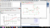
we are to make a pre-emphasis circuit with this response:

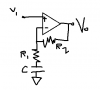
I used a simple rc filter to do it but it seems to be not working as expected..
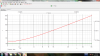
the gain at 2.12kHz is around 2.99dB, which is fine since its the specs...
the computed gain at 30kHz is 3+20log(30k/2.12k)=26dB..

but as can be seen on the picture, the gain @30kHz is 20log(99.52/9.96)=19.99dB
*(9.96 came from the flat line at low freqs, not show in the picture)... this is quite far from 26dB..

Any advice about getting the gain higher at 30kHz? One more thing, the slope isn't actually 20dB/dec, its around 17db/dec.. is this really like that in the real world?
 

Attachments

  • Capture.PNG
    Capture.PNG
    51.3 KB · Views: 308
  • pre-emp.png
    pre-emp.png
    246.9 KB · Views: 366
Your RC is feeding into a resistance instead of feeding into a very low impedance like the inverting input of an opamp.
Pre-emphasis for FM radio stations stops at 15kHz then a sharp lowpass filter cuts frequencies higher so that they do not beat with the 19kHz stereo pilot signal.

Try it like this (the sound source must have a very low impedance):
 

Attachments

  • pre-emphasis.PNG
    pre-emphasis.PNG
    4.8 KB · Views: 474
FM pre-emphasis standards vary from country to country. In North America, we use 75 microseconds as the RC time constant. In Europe, I believe that it is 50 microseconds. You already know this. I'm just adding it for beginners reference.

The 75 microsecond standard calls for a single pole filter (6dB/octave or 20dB/decade slope) and a corner frequency "f" of 2122 Hz, where 2*PI*f = 1/t and t = 0.000075. Simply put, The R in Ohms and C in Farads multiply to give you the time constant. Here is an illustration I made. Just adjust the values of R and C for your time constant.
deemphasis.PNG
You can also change the gain as needed. Note that the circuit marked "de-emphasis" is sensitive to driving impedance, which should be very low as compared with the value of the input resistor.
 
Last edited:
Your RC is feeding into a resistance instead of feeding into a very low impedance like the inverting input of an opamp.
Pre-emphasis for FM radio stations stops at 15kHz then a sharp lowpass filter cuts frequencies higher so that they do not beat with the 19kHz stereo pilot signal.

Try it like this (the sound source must have a very low impedance):


I tried it. here's the response.

then I put a simple low pass RC after it.. the response is still ugly...
 

Attachments

  • resp.png
    resp.png
    175.7 KB · Views: 252
I tried it. here's the response.
It is perfect. The rise is exactly 6db/octave like it is supposed to be.

then I put a simple low pass RC after it.. the response is still ugly...
You are not supposed to use a simple lowpass filter, it is supposed to be a sharp filter so that 15kHz is passed but 19kHz and higher are attenuated.
 
It is perfect. The rise is exactly 6db/octave like it is supposed to be.


You are not supposed to use a simple lowpass filter, it is supposed to be a sharp filter so that 15kHz is passed but 19kHz and higher are attenuated.


But what should I do for the "sharp filter"?
 
But what should I do for the "sharp filter"?
A sharp filter is many orders (many RC networks plus feedback from an opamp).
Years ago there were a few multi-order switched-capacitor Butterworth lowpass filter ICs available (I still have some National Semi ones) and I think today Maxim-IC have some.
 
my teacher said NO butterworth, chevychev, sallen key bessel... im stuck with first order so high cut-offs are off..

my classmates said they used this ckt. i solved for it and found that:
Vi/Vo=(sC(R1+R2)+1)/(sR1C+1)

and so i though it would be ok to use. but when i ran the simulation, many things are off:
1. 3dB point (for example @2.12kHz) isnt really 3dB
2. changing R2 is like changing the slope of the bode plot, its not exact 20dB/dec

the second effect is what I like since I can use it to change the gain at higher freqs(30k to 50k), but the real drawback is that the gain of lower frequencies also become higher.
care to explain what happened? varrying R2 should only change the knee frequency right? but why does it also change the slope?
 

Attachments

  • 113.png
    113.png
    6.3 KB · Views: 267
Status
Not open for further replies.

New Articles From Microcontroller Tips

Back
Top