Continue to Site

Welcome to our site!

Electro Tech is an online community (with over 170,000 members) who enjoy talking about and building electronic circuits, projects and gadgets. To participate you need to register. Registration is free. Click here to register now.

  • Welcome to our site! Electro Tech is an online community (with over 170,000 members) who enjoy talking about and building electronic circuits, projects and gadgets. To participate you need to register. Registration is free. Click here to register now.

FM Transmitter - Any suggestions/is it okay?

Status
Not open for further replies.

chiefwigms

New Member
**broken link removed**

Does that seem like it'll work?

The First op-amp is a preamp with a variable gain (~2-21) (controls deviation of the mic), followed by a summer that adds in a control voltage (for the tuning of the center frequency), followed by a low pass filter to let 0-15kHz out, followed by a 100 Mhz VCO that's adjustable. I'll have .1uF cap's on the op-amp's supply lines..

Any ideas/suggestions?

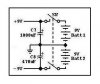
(Edit - Added new schematic to fix cap/mic voltage problem)
 
The principle seems OK, but I dont think you want to decouple the RF output, (pin2 of the oscillator module).

JimB
 
Hi Chief,
1) There are many ways that 3-wire electret mics are wired so I don't know if yours is correct. 2-wire electret mics have pins 1 and 2 on your mic connected together.
2) The values of your C1 and R2 are so high that their low frequency cutoff is only 0.07Hz! You won't believe how much rumble you'll get from traffic, air conditioning and wind noise.
3) The LMC662 is a Cmos opamp with their typical absolute max supply voltage of only 16V. Your 24V will blow it up! Cmos opamps are too noisy for a microphone preamp anyway.
4) Your FM oscillator has a deviation sensitivity of about 6V/MHz. Therefore your pot will tune about 60 station frequencies and won't have enough resolution to select only one. You don't have a limiter for your preamp so if you make a loud sound at the mic the oscillator will deviate over most of the entire FM band of 100 station frequencies!
5) Your 100MHz oscillator has such a wide tuning range that it is difficult to see how much its frequency reduces when it warms up by its high supply current. Maybe a couple of station frequencies. It is designed to be used in phase-locked-loop frequency-synthesizers where frequency drift by temp change doesn't matter.
6) Your circuit has a bunch of capacitors killing the oscillator's output instead of an antenna.
7) Your circuit doesn't have pre-emphasis so when heard on an FM radio that has normal de-emphasis its sound will not have any treble audio frequencies.
Nice try. :lol:
 
I'm a moron - those caps on the oscillator should be on VCC, not the output... didn't click till i looked again...


Any other suggestions?
 
Google has links to thousands of FM transmitter circuits, even mine.
Ask your teacher if you are allowed to copy someone else's circuit.

Does your teacher understand electronics enough to see the problems in the circuit you designed? Will you make your circuit and let your teacher try it?
 
Apparently not - I asked two of them, and they said it'd work fine, except that there'd be frequency drift. How much this affects the entire circuit, I have no idea.

This is the first wireless course I've taken (building circuits). I understand the theory, but never having experience piecing together components doesn't help. Looking up transmitters on google probably isn't the best idea either - Half the designs are probably just as bad (I'm not saying this because I'm lazy and don't want to search, but I'm sure there are so many different variations, that pin-pointing the best solution isn't really a good option). Plus, I think with this circuit, they are just trying to get me to understand the basics.. just transmit FM - this isn't production quality.
 
Hi Chief,
The difficult part of making an FM transmitter is making its oscillator with very short wires. Your oscillator is already made for you.
Your circuit will sort-of work, if you connect its microphone correctly.
I suggest replacing your 2.2uF C1 with 10nF (0.01uF) and replacing your 1M R2 with 100K, so it doesn't pass rumble frequencies, and replace your low-voltage opamp with a low-noise, regular voltage (up to 36V) TL072. :lol:
 
I'll give that a shot..

Initially I looked up a mic-preamp circuit which used a high pass that was 2.2uF w/ a 27k resistor..

My prof said the 27k wasn't enough input impedence for the op amp? I don't know, it seemed fine for me..

Thanks for the added input!
 
Hi Chief,
A 27K resistor and a 2.2uF cap will pass frequencies above only 2.7Hz. For voices, you need the high pass cutoff frequency to be about 100 times higher. Ask your teacher to teach you the simple formula.

The left opamp in your circuit will work the same with an input resistor to ground of just about any value. The input cap forms a high-pass filter with this resistor.
 
A simple thing got overlooked. the battery is SHORT CIRCUITED! (unless the top-left part of the diagram is not included in the circuit.

You dont connect ground directly to the +ve supply unless of course ground doesn't connect to -ve.
 
Hi MS,
Good observation! :lol:
I guess the short across the batteries is supposed to keep their juice from leaking out! :shock:

Chief probably meant to show that the negative terminal of the positive battery and the positive terminal of the negative battery are connected to ground. Therefore it is probably best to show all the battery terminals side-by-side like this:
 

Attachments

  • batteries.jpg
    batteries.jpg
    9.6 KB · Views: 757
Yeah - back in our ee labs in college, they always made us put the powersupply voltages at the top like that. I thought it was a standard or something.

There's no direct connection from VCC to ground though. Thanks for noticing!.

Also - I switched up the R/C on the high pass filter (to make the cut off ~ 300Hz). and am ordering the low noise jfet op amp that audioguru mentioned... Question though -

How would I know what my Vio is from the circuit (indetermining the type of TL072 I'd need)? Isn't this something you calculate with the op amp? (with the + input shorted to gnd and the output feeding to the -input (with a dmm between output to ground)?
 
Hi Chief,
One nice thing about FET-input opamps is that they don't have any input bias current, just a very small leakage current, so don't develop much of a Vio to get amplified. The input current of a TL072 is typically only 65pA so develops only 65uV across your circuit's very high value of 1M for R2.
The TL072 is inexpensive and doesn't have laser-trimming for its built-in Vio so it is typically 3mV like most ordinary opamps.

You shouldn't be worrying about offset voltage in your circuit. Its left opamp doesn't have any gain at DC and the right one has a gain of only 2. :lol:
 
Hi Chief,
The input offset voltage of the opamps will make insignificant difference in your circuit. Your tuning control has a range of 12V. 3mV, 6mV or even 10mV of offset voltage is so small if added to the tuning voltage or subtracted from it that you won't see any difference. You must adjust and readjust the tuning control anyway, far more than the tiny offset voltage, to compensate for the frequency drift of your oscillator as it warms up after being turned on or if the ambient temperature changes.
 
Status
Not open for further replies.

Latest threads

New Articles From Microcontroller Tips

Back
Top