Electro Tech is an online community (with over 170,000 members) who enjoy talking about and building electronic circuits, projects and gadgets. To participate you need to register. Registration is free. Click here to register now.
Welcome to our site! Electro Tech is an online community (with over 170,000 members) who enjoy talking about and building electronic circuits, projects and gadgets. To participate you need to register. Registration is free. Click here to register now.
C3 does not prevent the transmitter from working, it is the coupling capacitor for the voice. The transmitter is quiet when C3 is removed because there is no modulation.
The low value for R2 feeds a very high base current to the transistor.
The transistor has a very wide range of current gain, from 20 to 200.
If the gain of the transistor is 200, it is nearly saturated with its emitter at about 7.5V.
If the gain of the transistor is 20, the collector can't swing much because its emitter will be 4V.
I would use a 2N3904 transistor with 100k for R2. The transistor's and battery's current will be much lower and the transistor's input impedance will be much higher.
I would use a 2N3904 transistor with 100k for R2. The transistor's and battery's current will be much lower and the transistor's input impedance will be much higher.
I was avoiding the 2N3904 because it's fT is < 600Mhz, and I'm afraid that any transistor that can't process high frequencies will not start (unless there is something else I fail to understand with them).
I'll try your idea, but doesn't the 100K make the transmitting range lower?
The oscillator doesn't have much power because the transistor is turned on too much and the emitter resistor wastes power at high current. You can't reduce the value of the emitter resistor much, or you will need to increase the value of the feedback capacitor so it isn't loaded down. Then the larger feedback capacitor would load down the tank and also lower the frequency of the oscillator.
If you want more output power, then add a tuned-collector amplifier transistor without an emitter resistor. Then the antenna will be on the amplifier, reducing its frequency-changing effects on the oscillator.
Do you have a regulated supply for the oscillator? Its frequency changes when the supply voltage changes, like when a battery's voltage runs down. The transistor's capacitance changes when the supply voltage changes.
Is there an equation that indicates the capacitor value required based on the emitter resistor or vice versa?
If you want more output power, then add a tuned-collector amplifier transistor without an emitter resistor. Then the antenna will be on the amplifier, reducing its frequency-changing effects on the oscillator.
The feedback capacitor plus the transistor's capacitance plus stray capacitance forms a voltage divider with the emitter resistor. In my FM transmitter's oscillator, if I reduce the emitter resistor to 47 ohms for a higher power output then the transistor would need a gain greater than 4 to oscillate.
I don't want to deal with two controls to adjust the frequency.
In my FM transmitter, the tuned circuit in the output amplifier is broad enough to cover the entire 20MHz band, because the antenna's impedance is so low it damps the tuned circuit.
If you need to tune a broader band then use a two-gang capacitor like in radios.
The feedback capacitor plus the transistor's capacitance plus stray capacitance forms a voltage divider with the emitter resistor. In my FM transmitter's oscillator, if I reduce the emitter resistor to 47 ohms for a higher power output then the transistor would need a gain greater than 4 to oscillate.
MStechca,
Don't you know that an oscillator needs a gain of more than 1 to oscillate?
If you use a voltage divider to reduce the feedback signal to 1/4, then the transistor needs a gain of more than 4 to oscillate.
The tank at the collector is a high impedance parallel LC circuit, therefore affects frequency not output level. If its impedance was zero then the output would be zero and the circuit wouldn't oscillate.
The antenna has a low impedance but the small coupling capacitor in series with it has a higher impedance so reduces the antenna's loading effect on the circuit. Many transmitters use a tap on the tank's coil or a seies-tuned LC circuit to match the antenna.
I don't understand why, when the tank, the positive feedback capacitor and the emitter resistor are all in series from VCC (or +ve) to ground.
If the emitter resistor and the impedance of the capacitor affect gain requirements, then I think the impedance of the LC circuit should be included. If not, then what can I use the impedance of the LC circuit for?
I found out something interesting.
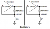
I replaced the emitter resistor with a 0.1uH inductor and a 100 ohm resistor in series. at the point where the new inductor and the new resistor connect, I connected a 3nF capacitor from that point to +ve.
I also reverted back to the PN3563 transistor. I changed the resistor connected to the NPN's base to 150K. I attached the antenna to the emitter of the NPN. It seems that the stability is greatly improved, BUT the output was not what I wanted. Instead of picking up dead air, I obtained a continuous tone. It seems that the capacitor connected to the NPN's base affects the frequency of the tone.
When I added a basic common emitter amplifier stage to my new design, the results were ok (I could pick up some sound coming from the speaker), but the tone is still there.
If there is a specific frequency for "dead air" (please don't say 0 hz), please let me know.
You don't have an RF supply bypass cap in your circuit so who knows what is the inductance of your 1mF electrolytic audio bypass cap.
Since your radio heard a tone, then the transmitter is sguegging, or being cut-off at an audio frequency. All RF circuits should have an RF bypass cap which would be a 1000pF ceramic disc with very short wires.
I don't know why you added a choke in series with the emitter, it drastically reduces the gain at RF. Bypassing the choke with a cap to ground would just short the choke at RF. Bypassing the emitter resistor with a cap to ground would short the feedback to ground.
The parts aren't considered to be in series from the supply to ground because the transistor in the circuit changes things.
A radio hears "dead air" from a transmitter when the trasmitter isn't modulated, or when the radio is overloaded. Isn't your "radio" an easily overloaded super-regen?
You didn't hear me. An electolytic cap is an inductor at your high frequency. It might have just enough capacitance between its wires to allow your circuit to work. A 1000pF ceramic disc cap with very short wires is far better as an RF supply bypass. The cap should be across the supply terminals of your pcb, not at the battery. Each inch of wire adds inductance in series with it.
I even went to 1000uF (not pF) for the supply bypass cap and I didn't notice much of a difference.
The bigger is the cap, the higher is its inductance. Inductance is the opposite of the capacitance that your circuit needs.
A battery could have an internal resistance of 100 ohms or more. A 1000pF ceramic disc cap has an impedance of only 0.8 ohms at 200MHz.
The RF gain is not reduced by adding an inductor in the emitter circuit. In fact, gain should be increased, since this is a common-base circuit as far as the oscillator is concerned. As an extension of this concept, the oscillator should run with a current source supplying emitter current. It oscillates in simulations with an inductor or a current source, and I don't see why it should not also work in hardware.
The RF gain is not reduced by adding an inductor in the emitter circuit. In fact, gain should be increased, since this is a common-base circuit as far as the oscillator is concerned.
I see what you mean. The high impedance of an inductor in series with the emitter allows the total feedback signal to go into the emitter, instead of dividing some into an emitter resistor. Also, the low resistance of an inductor allows low DC voltage drop so the transistor gets the full supply voltage allowing more output power.
The emitter is a low impedance so the addition of an inductor instead of a resistor will make only a small improvement.
I think that DC emitter degeneration would still be required for bias stability.
at the point where the emitter inductor and the resistor meet, I hooked up a basic RC common emitter amplifier, and the two transistors are both PN3563's. It seems that I am obtaing better results, but I still need to obtain the perfect pull-up resistor and coupling capacitor.
Not bad, considering that I am literally using a common emitter amplifier to attempt (quench?) frequency modulation. :wink:
Amplitude modulation occurs in your FM transmitter because the input modulating signal causes the collector and emitter voltages to change.
Frequency modulation also occurs in your FM transmitter because the collector-emitter capacitance changes when the transistor's collector and emitter voltages are changed by the modulation (and by changes in the supply voltage).
This site uses cookies to help personalise content, tailor your experience and to keep you logged in if you register.
By continuing to use this site, you are consenting to our use of cookies.