Continue to Site

Welcome to our site!

Electro Tech is an online community (with over 170,000 members) who enjoy talking about and building electronic circuits, projects and gadgets. To participate you need to register. Registration is free. Click here to register now.

  • Welcome to our site! Electro Tech is an online community (with over 170,000 members) who enjoy talking about and building electronic circuits, projects and gadgets. To participate you need to register. Registration is free. Click here to register now.

Generating waveform for 74LS93

Status
Not open for further replies.

hypersnapper

New Member
74LS93 not showing any pattern as a counter

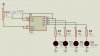
Hi, I would like to see waveforms using oscilloscope on Qa, Qb, Qc, and Qd in Proteus for the circuit I attached below but I can't see it not showing any pattern. Can you help me determine the problem? Thank you.
 

Attachments

  • 7493n.JPG
    7493n.JPG
    44.9 KB · Views: 2,715
Last edited:
An old 74LSxx part has pretty good minimum output low current of 8mA but has almost no output high current (a minimum of only 0.4mA).
It also has not much output high voltage (a minimum of only 2.7V).
Your schematic shows a 7493, not a 74LS93 which is different.

So it might not light your LEDS when the outputs go high and the output that also drives the CK2 input might not have a logic high voltage high enough.

audioguru thanks for replying, originally I was using 74ls93 but seen not working so changed it to 7493 but still the same. I'm changing it back to 74ls93, anymore suggestions to make it work?
 
Use a 74HC93 high-speed Cmos IC. It has outputs that can source or sink up to 25mA.

One or both RESET pins must be connected to 0V for the counter to count.
 
Thank you again audioguru I tried it. I realized the problem was R01 and R02 should be connected to ground. sorry a little error :)
 
Status
Not open for further replies.

Latest threads

New Articles From Microcontroller Tips

Back
Top