Hi,
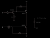
I'm designing an h-bridge using BD679 / 678 darlington transistors and 2N2222 or BC337. I know there are lots of available designs on the net, but i didn't find one that uses those parts (I'm having about 30 of'em, then those are the ones that i'll use and I would like to correct my design mistake). The schematic is attached it was drawn and simulated in falstad.com's simulator.
The circuit will be run on 5V for logic and 12 to 24 volts to power the load. According to the simulator, the circuit works fine at 5V, but when I raise the source voltage to 12V or so, I get huge voltage drop on the output, the circuit is acting as a voltage divider. I would appreciate that someone points me to the mistake. Could it be run at a range from 12 to 24 or should I add potentiometers to tune it for each voltage.
This is the schematic's source in case someone wants to load it in the simulator (File - Import, then paste the source)
Yes, maybe it's so stupid as problem, but I'm not good enough in electronics to avoid such a mistake.
PS: The gain of the BD679 is 750 and it's intended to be used for currents up to 2 amps (4A peak).
Thank you.
I'm designing an h-bridge using BD679 / 678 darlington transistors and 2N2222 or BC337. I know there are lots of available designs on the net, but i didn't find one that uses those parts (I'm having about 30 of'em, then those are the ones that i'll use and I would like to correct my design mistake). The schematic is attached it was drawn and simulated in falstad.com's simulator.
The circuit will be run on 5V for logic and 12 to 24 volts to power the load. According to the simulator, the circuit works fine at 5V, but when I raise the source voltage to 12V or so, I get huge voltage drop on the output, the circuit is acting as a voltage divider. I would appreciate that someone points me to the mistake. Could it be run at a range from 12 to 24 or should I add potentiometers to tune it for each voltage.
This is the schematic's source in case someone wants to load it in the simulator (File - Import, then paste the source)
Code:
$ 1 0.0 3.3115451958692312 69 5.0 50
L 384 352 352 352 0 0 false 5.0 0.0
L 400 560 352 560 0 0 false 5.0 0.0
r 464 352 384 352 0 1000.0
r 480 560 400 560 0 1500.0
t 480 352 512 352 0 1 -4.99999998495 -2.5000000000000004E-11 50.0
t 640 336 688 336 0 -1 2.4999999849999996 -1.5000000352927145E-8 750.0
g 512 448 512 464 0
t 640 560 688 560 0 1 -2.4999999999261084 7.389162561518192E-11 750.0
g 688 656 688 688 0
w 480 560 640 560 0
w 688 576 688 656 0
w 688 544 688 352 0
w 496 656 496 560 0
w 480 560 496 560 0
w 512 336 544 336 0
w 640 336 608 336 0
w 688 320 688 224 0
w 688 272 688 320 0
w 480 352 464 352 0
R 688 128 688 96 0 0 40.0 5.0 0.0 0.0 0.5
w 688 128 688 224 0
O 800 432 848 432 1
w 800 432 688 432 0
w 688 432 688 352 0
w 672 272 688 272 0
r 800 432 800 544 0 1.0
R 800 576 832 576 0 0 40.0 2.5 0.0 0.0 0.5
w 800 576 800 544 0
x 823 498 883 502 0 15 ohm load
x 872 438 966 442 0 15 Output voltage
x 624 543 669 547 0 15 BD679
x 626 370 671 374 0 15 BD678
x 461 324 511 328 0 15 2N2222
r 512 384 512 448 0 1500.0
w 512 368 512 384 0
w 544 336 608 336 0
x 415 374 434 378 0 15 R1
x 475 426 494 430 0 15 R2
x 429 584 448 588 0 15 R3
r 496 656 688 656 0 100000.0
r 544 272 672 272 0 100000.0
w 544 272 544 336 0
o 21 64 0 34 20.0 9.765625E-5 0 -1
Yes, maybe it's so stupid as problem, but I'm not good enough in electronics to avoid such a mistake.
PS: The gain of the BD679 is 750 and it's intended to be used for currents up to 2 amps (4A peak).
Thank you.