Continue to Site

Welcome to our site!

Electro Tech is an online community (with over 170,000 members) who enjoy talking about and building electronic circuits, projects and gadgets. To participate you need to register. Registration is free. Click here to register now.

  • Welcome to our site! Electro Tech is an online community (with over 170,000 members) who enjoy talking about and building electronic circuits, projects and gadgets. To participate you need to register. Registration is free. Click here to register now.

help fixing trunk switch

Status
Not open for further replies.
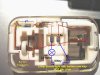
this would be the setting, correct?
**broken link removed**

with that setting, one way it come up about ".605" and the other way it continues to show "1."

With the setting you are showing and the "1" meaning out of range for that particular scale, I'd say the diode is good and has 0.605v drop in the forward direction.
The test current for the diode test may be 1 mA; it'll be in the specs for your meter.
My meter reads "OL" for "overload" when I'm out of range.

I'd look for something in the switch that is loose or worn, an adjustment of some kind, that prevents a good bulb from lighting.

You may need a schematic for your vehicle's circuitry that interfaces with this trunk circuit; this diode may be there for current steering and so the problem may be elsewhere.

i dont know where else the problem could be. im getting 12v from the harness that connects to that assembly. if you look at the first pic i posted, look towards the left, to the left of the bronze piece theres that white piece of plastic with a metal ball. that is the lever that moves. that is the on position. it moves up into the empty space above it when in the off position. so i do not think it is the switch itself.
 
i dont know where else the problem could be. im getting 12v from the harness that connects to that assembly. if you look at the first pic i posted, look towards the left, to the left of the bronze piece theres that white piece of plastic with a metal ball. that is the lever that moves. that is the on position. it moves up into the empty space above it when in the off position. so i do not think it is the switch itself.

It's puzzling.
Usually that means we are assuming something that isn't true. Finding out what that is might be difficult.
The only good thing about these kinds of problems is that, for sure if you solve it you're going to learn something new.

What component can't it be? Why can't it be that?

Maybe there is invisible non-conductive grime on the contacts that isopropyl alcohol would clean off?

Maybe there is an intermittent in the wire, so the symptoms change with time?

If you hook up a known-good bulb with clip leads [first buff the bulb contacts with a mild abrasive] so the switch/connector mechanism is not hidden by the bulb, can you trace through the whole circuit path with a voltmeter and see if there is 12v across a (hidden) gap, a break, a stress fracture?

Maybe the bulb being held in place by the springy contacts opens a microgap that closes when there is no bulb in place?
 
hi snwsk8r8,
Its seems we disagree on the problem.:)

One way to be 100% sure that the complete switch mechanism and diode are working OK is to do the test shown in the attached image.

Use a separate low voltage lamp and battery to suit.
If the switch/diode is OK the lamp will light when the battery is connected one way and not the other.

Using a lamp rather than a meter will send more current thru the switch/diode which may show up any bad riveted joints/welds/contacts etc.
It would be a good idea to work the plunger switch while doing the test.

If the test shows OK, then the problem is elsewhere in the car wiring.

I have enhanced your original image.
 

Attachments

  • Trunk1.jpg
    Trunk1.jpg
    118 KB · Views: 121
Status
Not open for further replies.

Latest threads

New Articles From Microcontroller Tips

Back
Top