roberto_manero
New Member
so im creating a temp. operated alarm/switch could you please help me on how to change some parts
since one of my part have been old i have to replace it...
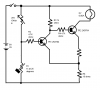
from 2N3704.... to BC548 (thanks to Lord Loh) However the collector current of the BC548 is limited to 100mA while 2N3704 is capable of 500mA.
so below is the schem. and i dont know how to use a sim... T_T
please help me...
thanks
since one of my part have been old i have to replace it...
from 2N3704.... to BC548 (thanks to Lord Loh) However the collector current of the BC548 is limited to 100mA while 2N3704 is capable of 500mA.
so below is the schem. and i dont know how to use a sim... T_T
please help me...
thanks
")
