I have a PM 24V, 17A, 2 wire blower motor for a kit plane I'm building. Am currently using a Critical Velocity PWM controller. It is very noisy, have tried caps, twisted wires, etc. I want to use the circuit that's in my car, a Honda, upgrading the components. I believe it's an open loop/feedback with Power Transistor circuit. Or is this what's known as emitter/follower? The circuit as depicted in the schematic from the manual does not show the blower switch.
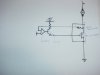
The car has a momentary on-off-on switch with a chain of 7 vertical green LED's that illuminate if you increase blower speed and extinguish as you decrease rpm. This circuit will be operating off of 24VDC. Can the momentary switch be operated off a Digipot? I am attaching a drawn diagram off the circuit(from the manual). If someone could explain where/how the switch is connected as well as the rest of the circuit it would be greatly appreciated.
Thanks,
Pat