Continue to Site

Welcome to our site!

Electro Tech is an online community (with over 170,000 members) who enjoy talking about and building electronic circuits, projects and gadgets. To participate you need to register. Registration is free. Click here to register now.

  • Welcome to our site! Electro Tech is an online community (with over 170,000 members) who enjoy talking about and building electronic circuits, projects and gadgets. To participate you need to register. Registration is free. Click here to register now.

Help with monostable NE555 circuit

Status
Not open for further replies.

whitelamp12

New Member
Hi, I'm having trouble with the following and help is appreciated:

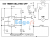
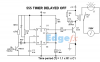
I'm automating a very very simple irrigation system without a micro, instead I used a monostable circuit with a NE555 so that the irrigation would take place once a day. My monostable circuit needs a single pulse that is given by a push button to trigger a relay for 14 seconds, but I would like to use the positive transition given by a wall mounted AC timer to trigger my monostable circuit. The timer will be on for 12 hours before completing the pulse and turning off.

The circuit I used is in the attachment
 

Attachments

  • Screen Shot 2013-04-02 at 11.47.12 PM.png
    Screen Shot 2013-04-02 at 11.47.12 PM.png
    64 KB · Views: 276
hi,
Add the components as shown on this image.

Let me know the details of the positive input transition and will work out the value of Rb on the transistor input.

E.
 

Attachments

  • Image1.png
    Image1.png
    58.1 KB · Views: 369
Hi.

The positive transition comes from the wall mounted 120V AC timer and then switched to a 12V DC grounded transition through a relay.**broken link removed**
The image shows kind of what I would like to accomplish; to use the transition of the 120V timer to activate the 555, the problem is that I need to find a way to interrupt the transition from the wall mounted timer so it gives me a complete pulse.

Hope I've explained myself well, if you have any question please do make them. Thank you in advanced!
 
If you apply a positive pulse to a capacitor, won't you get a negative pulse on the other terminal which should be enough to trigger a 555?

View attachment Draft1.asc

John

Here's a screen print,in case the asc doesn't work.

Untitled-1.png
 
Last edited:
hi W12.
I cannot open your attachment on Post #3.??
 
... the problem is that I need to find a way to interrupt the transition from the wall mounted timer so it gives me a complete pulse.!

Do you want the 555 monostable to make its 14second cycle when the 12 hour wall clock first turns on, or as it turns off at the end of the 12 hours?

Question about the relay used between the wall-clock and the 555 circuit. Does it have a Normally-Open or Normally-closed set of contacts? Is that set of contacts isolated from any other loads so connected only to the 555 circuit?

Dear MikeMi, the relay would be connected in the normally open switch, because I want that when the wall clock turns on it sends the transition to something that gives me the complete pulse. Here is a link to what I'm trying to accomplish, doesn't have to be like that, but it's what I have in mind.

https://www.dropbox.com/s/8pxoq4lttdvmzsq/Timer.png

You didn't answer the questions I posed. Forget about the circuit you linked. Answer these questions:

Do you want the 555 monostable to make its 14second cycle when the 12 hour wall clock first turns on, or as it turns off at the end of the 12 hours?

Does the 120Vac relay that you are using between the wall-clock timer and the 555 circuit have a Normally-Open or Normally-closed set of contacts? Both?


Is that set of contacts isolated from any other loads so connected only to the 555 circuit?
 
Here is a hack at what I think you asked for:

In the process I think I came up with a novel way of using a 555 as a positive-edge-triggered one-shot. Never built it, but am confident it will work as simulated.

In the simulation, the signal V(timer) [Green Trace] is a proxy for what the AC wall-clock timer does, except for convenience I made it be on for 120s and off for 120s instead of 12h and 12h, respectively. I'm assuming that the AC wall-clock timer controls a relay, which provides a contact closure as long as the AC wall-clock timer output is on.

That NO contact is shown as "S2" and "relay" in the schematic. It switches the left end of the timing capacitor C1 to ground while the AC wall-clock timer output is on, triggering the 555, initiating the timing cycle of 15sec as shown by V(rc) [Red Trace], and pulling-in the 555 output relay as shown by I(L1) [Blue Trace]. When the AC wall-clock timer relay turns off, diode D1 clamps the voltage at node "rc" one diode drop above Vcc.

Note that as long as the AC wall-clock timer duration is at least 15s, then it doesn't matter how long the duration is, even if it lasts 12h. The 555 output pulse duration is slightly longer than R1*C1.

C2, C3 and C4 are required bypass caps. D2 is a snubber for the output relay. As mentioned earlier, S2 is the NO contact controlled by the external 12h timer.
 

Attachments

  • NoneShot.jpg
    NoneShot.jpg
    325.1 KB · Views: 219
Last edited:
Status
Not open for further replies.

Latest threads

Back
Top