[image]http://www.envero.net/images/Fullbridge.jpg[/image]
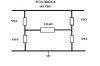
Given above is a sample H/Full bridge, . I want to detect the phase difference between the current through the load and the voltage developed acroos it . Once this is done the output would be sent to a control circuit which would be programmed to increase or decrease the switching freq of the switches depending on the phase difference between the current and voltage.
Now I have no experience in digital electronics (i am more of a power electronics guy) and the whole phase detection business is driving me crazy .
What i have done is added diode clippers(schottky) that would clip the output voltage to somewhere around 0.4V (coz any phase detection device cannot handle the voltage across the load)
NOW IS THE MILLION $$$$ QUESTION
HOW DO I DETECT CURRENT AS WELL AS THE VOLTAGE JUST USING A SINGLE DEVICE (FOR EG A COMPARATOR????).....
GUYS PLZ HELP ME OUT OVER HERE ....REALLY NEED THIS !!!!!
CHEERS!!!