Continue to Site

Welcome to our site!

Electro Tech is an online community (with over 170,000 members) who enjoy talking about and building electronic circuits, projects and gadgets. To participate you need to register. Registration is free. Click here to register now.

  • Welcome to our site! Electro Tech is an online community (with over 170,000 members) who enjoy talking about and building electronic circuits, projects and gadgets. To participate you need to register. Registration is free. Click here to register now.

How do I start a business selling PCB Boards?

Status
Not open for further replies.
There are lot's of options out there, so it would depend if yours did something I wanted that others didn't, and if it was competitively priced. However, I've never bought any such boards - I would usually simply design my own - but I've not used a Nano, but do use Pro Mini's. In fact I've just had boards come from China last week using Pro Mini's for converting my cordless tools battery chargers to Li-Ion - with the board designed to replace the existing one in the chargers. I based on a design I found, and was going to port it to a PIC - but then thought "what's the point", as there's plenty of board space available.

Edit:

Here's an example, only £2.51
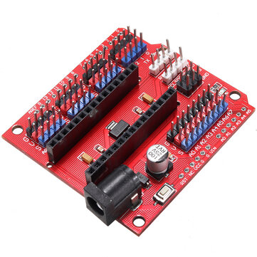
Right I completely understand, my intention is to solve the problem of people building products to make it easier to build projects. Which is why I am building this. So I wanted to know if this really does solve the problem I intend to solve, so which is why I thought of posting it here.

But this board is just to connect other peripherals with a wire, but for example, someone might need to solder their Accelerometer and Gyroscope to a fixed surface, then my board has the provision to do so, which isn't on the one you suggested. It is for the user to have a common board to house all their sensors and easily wire other peripherals.
 
I'm not sure you're headed in the right direction, but....

I have a few suggestions to improve your board based on my experiences.

Mounting hole clearance
There's not much clearance to connectors at two of the mounting holes, and a standoff or nut will cover some of your labels. To remind myself to leave enough clearance, I designed a mounting hole component that shows the clearance for a nut and clearance needed for a nut driver in the document layer. It doesn't show up on the finished board, but it's a reminder when laying the board out.

Trace Spacing
There are a few places where traces are needlessly close together. Where there's room, spread things out more.

Vias
The vias look tiny. I suggest making them a little larger. As a rule, don't push the fab house's limits where you don't have to - sometimes reliability suffers when pushing their limits.

Corners
PCB corners are sharp. Rounding them slightly makes the board more comfortable to handle.

Lock Footprints
As people with less experience may be assembling these boards, use lock footprints for the headers. These were designed by a guy at Sparkfun; staggering the holes slightly holes a header perpendicular to the board to make soldering easier.

et brd critique.jpg
 
Last edited:
Thanks for the information! I appreciate that you take your time and explain everything in detail, it is very helpful. By the way, in my opinion, if you are selling something is better to also have a site where are all your products and also a little description of them. I think it will benefit your selling. Nowadays, it is not so difficult to build your own site as everything is available on the Internet. Firstly you need to read some Sitebuilder Reviews, then you need to start building it.
 
Last edited:
I'm not sure you're headed in the right direction, but....

I have a few suggestions to improve your board based on my experiences.

Mounting hole clearance
There's not much clearance to connectors at two of the mounting holes, and a standoff or nut will cover some of your labels. To remind myself to leave enough clearance, I designed a mounting hole component that shows the clearance for a nut and clearance needed for a nut driver in the document layer. It doesn't show up on the finished board, but it's a reminder when laying the board out.

Trace Spacing
There are a few places where traces are needlessly close together. Where there's room, spread things out more.

Vias
The vias look tiny. I suggest making them a little larger. As a rule, don't push the fab house's limits where you don't have to - sometimes reliability suffers when pushing their limits.

Corners
PCB corners are sharp. Rounding them slightly makes the board more comfortable to handle.

Lock Footprints
As people with less experience may be assembling these boards, use lock footprints for the headers. These were designed by a guy at Sparkfun; staggering the holes slightly holes a header perpendicular to the board to make soldering easier.

View attachment 133527
Thanks for the suggestions, but would like to know your reason as to why I am not heading in the right direction? Would like to know your point of view
 
Status
Not open for further replies.

Latest threads

New Articles From Microcontroller Tips

Back
Top