Hi iGuys,
I wired two different circuits both with voltage regulators and not getting the results I was hoping for and looking for insight on what I'm doing wrong.
**broken link removed** is a 24VAC rectified to 24DC. The rectifier I'm using is GBU605 and the voltage regulator is a 78248T. I couldn't find either in LTSpice so I used whatever I could find to for illustration purposes.
I get 35.4VDC at the input of the voltage regulator and the output is exactly the same with no change. Also the regulator gets quite hot and I mean burning hot. I can see that the maximum input voltage in the datasheet is 35VDC is that the reason?
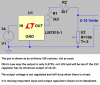
The **broken link removed** is a 0-10 volt simulator. I had one made for a 24VD supply with a 14K resistor and a 10K POT which worked fine but it was as inaccurate as the input voltage was so I thought I could make one with a voltage regulator to get a steady input and therefore a closer accuracy of 0-10VDC out of the POT.
What I get out of the 7815CT regulator is 15.06VDC without the 10K POT in the circuit but as so as I add the POT the voltage out of the regulator drops to 14.66 with the POT at maximum resistance of 10K. I also do not get the 0-10VDC I expected at output of what is a voltage divider between 5000K resistors(3.3K+2.7K) and the 10K POT. I only get 8.96VDC. Where am I going wrong?
Thanks
Kal
I wired two different circuits both with voltage regulators and not getting the results I was hoping for and looking for insight on what I'm doing wrong.
**broken link removed** is a 24VAC rectified to 24DC. The rectifier I'm using is GBU605 and the voltage regulator is a 78248T. I couldn't find either in LTSpice so I used whatever I could find to for illustration purposes.
I get 35.4VDC at the input of the voltage regulator and the output is exactly the same with no change. Also the regulator gets quite hot and I mean burning hot. I can see that the maximum input voltage in the datasheet is 35VDC is that the reason?
The **broken link removed** is a 0-10 volt simulator. I had one made for a 24VD supply with a 14K resistor and a 10K POT which worked fine but it was as inaccurate as the input voltage was so I thought I could make one with a voltage regulator to get a steady input and therefore a closer accuracy of 0-10VDC out of the POT.
What I get out of the 7815CT regulator is 15.06VDC without the 10K POT in the circuit but as so as I add the POT the voltage out of the regulator drops to 14.66 with the POT at maximum resistance of 10K. I also do not get the 0-10VDC I expected at output of what is a voltage divider between 5000K resistors(3.3K+2.7K) and the 10K POT. I only get 8.96VDC. Where am I going wrong?
Thanks
Kal
")