Continue to Site

Welcome to our site!

Electro Tech is an online community (with over 170,000 members) who enjoy talking about and building electronic circuits, projects and gadgets. To participate you need to register. Registration is free. Click here to register now.

  • Welcome to our site! Electro Tech is an online community (with over 170,000 members) who enjoy talking about and building electronic circuits, projects and gadgets. To participate you need to register. Registration is free. Click here to register now.

how to controll volume in a 1W stereo amplifier

Status
Not open for further replies.

electronito

New Member
Hi there,

I just built a 1W Stereo Amplifier Module to use with my bent toy instruments and I want to be able to control the volume. The information sheet that came with the kit says to use speakers with a minimum of 1W, 4 or 8 Ohms. My first question is, can i use a 40W 6 Ohms speakers with it? Will it produce unwanted noise?

And my most needed help comes with the audio taper pot I should use inserted somewhere in the middle of the cable (an Y adapter Audio cable: in one side a 1/8 plug and in the other sides two RCA plugs, left and right) that goes connected from the bent instrument's output to the INPUT RCA jacks on the amplifier. i know radioshack sells the "100k dual-ganged stereo volume control" but I do not know if 100k is too much. Does anybody knows if I need a 5-25k stereo volume control instead?

thanks
 
electronito said:
The information sheet that came with the kit says to use speakers with a minimum of 1W, 4 or 8 Ohms. My first question is, can i use a 40W 6 Ohms speakers with it? Will it produce unwanted noise?
Your 6 ohm speaker is between 4 ohms and 8 ohms so is fine. Your speaker is rated for more than 1W so won't be damaged by playing at 1W. 1W isn't very loud. If you try to turn up the volume higher than 1W then there will be high distortion.

i know radioshack sells the "100k dual-ganged stereo volume control" but I do not know if 100k is too much. Does anybody knows if I need a 5-25k stereo volume control instead?
Attach the schematic of the amplifier for us to see what resistance is suitable for a volume control.
 
thanks audioguru, i really appreciate it.

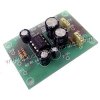
here are some schematic and color image.:)

View attachment amplifier diagram (1).pdf

color photo.jpg
 
You should be able to substitute a dual audio taper 10K pot for the two 10K resistors to ground. Audio input to the clockwise end of the resistive tracks. CCW ends to ground. Wipers to IN1+ and IN2+.

You could probably use anything from 5K to 25K, depending upon the input stage of your amplifier chip. It is remotely possible that the biasing of the input stage might be upset with the modified source resistance that the amplifier will see as you vary the gain setting. Measure the DC voltage across the existing 10K resistors before making any modifications. If there is a DC voltage of more than a few millifvolts, you may have to insert a series resistor of, say, 5K between the pot wiper and the + inputs to be sure you don't cause problems inside the chip as you pull the input to ground with the pot.

Never hurts to download the specification sheet and app notes for the IC from the manufacturer or third-party spec sheet suppliers. They might tell you if there are any restrictions on the permissible resistance to ground at the input.
 
Last edited:
It is a stereo amplifier project. The Samsung IC gives about 1/2W per channel, which might be enough to be barely heard. The datasheet shows the same circuit.
 
Hi,
thanks a lot. I am new to electronics so let's see. I will try to implement a 10K audio/log potentiometer in the middle of a " 6ft gold series phono-to-1/8"-Y adapter" from radio Shack. This cable would go from the output of the instrument to the input of the amplifier. Please correct me if you see I am wrong.This is an image of the cables:
pRS1C-2266520w345.jpg

Because I am new to electronics I have to think things several times. I found these images in the internet that explain visually how to implement the potentiometer in the middle of the cable, mentioned above, to an amp.
04.jpg
05-1.jpg
These images can be found at:http://www.oscarcontrols.com/volume/index.shtml
I suppose that following these images and what Awright wrote I can hit the target.

Also the data sheet of the amp is at;
http://pdf1.alldatasheet.com/datasheet-pdf/view/37147/SAMSUNG/KA2209B.html
I tried to attach an image of the block diagram directly to this email but it was impossible.

I will try to implement the pot following what I wrote about and if you see it is not right please let me know. I would appreciate it.
 
Well, the good news is that "Test Circuit 2" in the spec sheet shows pin 6 (non-inverting input) grounded and the inverting input capacitively coupled. This indicates that the bias of the input stage will not be disturbed by bringing the non-inverting input pin to ground with your gain pot.

They say that the input resistance of the IC is 100K, so anything from 5K to 25K should be fine for the input pot. Generally speaking, higher pot resistance is better to minimize loading of the signal source. On the other hand, you don't want the pot resistance to be excessively loaded by the input resistance of the amplifier. With a 25K pot, its source resistance to the amplifier is highest at 50% rotation (assuming a low-impedance signal source). This places the two halves of the pot in parallel to (virtual) ground impedance for a 6.25K source impedance from the pot. This will not be excessively loaded by the 100K input resistance of the amplifier.

How are you going to use this amplifier? If it is going to be used in "the field," that is, being carried around and not in a fixed location, having the pots in the middle of the input cables is asking for trouble due to wire fatigue, accidental contact with the input conductor with resulting hum, etc. I would recommend putting the circuit and the gain pots in a project box available from many electronics suppliers like Digi-Key, Mouser, or possibly even Radio Shack. Metal provides better shielding, but for the low gain of this amplifier, a plastic box may be fine and no worse than hanging out in the breeze.

While 1/2 watt is certainly not going to give you much undistorted volume on home HiFi (do they still use that term?) speakers or a PA system, it will be adequate for personal listening in a quiet environment and it is a good introductory project.

Have fun.

awright
 
Thanks very much Awright. i got it. I built it and it works. I just have to place the amp, the two speakers and the volume control in a unique box to carry around.

see you next
 
Status
Not open for further replies.

Latest threads

New Articles From Microcontroller Tips

Back
Top