Continue to Site

Welcome to our site!

Electro Tech is an online community (with over 170,000 members) who enjoy talking about and building electronic circuits, projects and gadgets. To participate you need to register. Registration is free. Click here to register now.

  • Welcome to our site! Electro Tech is an online community (with over 170,000 members) who enjoy talking about and building electronic circuits, projects and gadgets. To participate you need to register. Registration is free. Click here to register now.

How to Create a 12V Breathing/Fading LED Circuit with My Current Components?

StrayDoggo

New Member
Hi everyone,


I'm working on a project to make an LED that fades in and out (breathing effect) and operates on a 12V power source. I have the following components:


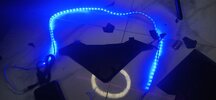
12v strip led
3x 3.7v batteries connected in series = 12v (with added extra voltage when fully charged resulting in 12v)


BC547 NPN Transistor
NE555 Timer
C817 Optocoupler
330uF 50V Capacitor
330uF 25V Capacitor
1000uF 25V Capacitor
1000uF 50V Capacitor
100k Potentiometer
15K Ohm 1/4W Resistor
10K Ohm 2W Resistor
100K Ohm 1/4W Resistor
1K Ohm 1W Resistor
4.7K Ohm 1/4W Resistor


Could someone guide me on how to wire these components to achieve the breathing effect? If any additional components or specific values are needed, I'd love some advice. I’d also appreciate any example circuits or explanations on how to calculate the timing for smooth fading.


Thanks in advance for any help!

I am not very good with circuit diagrams I am a visual learner, I also checked youtube but it didn't help me much and it was over complicated.
 

Attachments

  • IMG_20240825_231825.jpg
    IMG_20240825_231825.jpg
    1.4 MB · Views: 44
  • IMG_20240825_211825.jpg
    IMG_20240825_211825.jpg
    1.2 MB · Views: 48
Schematics are the language of electronics.
If you would like to pursue electronics as a hobby, you MUST learn how to read schematics.

This is similar like a mechanical engineering, not knowing how to read a mechanical drawing.
 
Schematics are the language of electronics.
If you would like to pursue electronics as a hobby, you MUST learn how to read schematics.

This is similar like a mechanical engineering, not knowing how to read a mechanical drawing.
Yeah I know that. This is a hobby of mine and I have done many projects and experiments based on hands-on try outs. Never had to nor ever used any schematics.

I guess I have to learn the basis now.
 
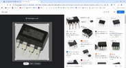
I have a question, what's the IC they are using in the schematics?

Is it this? NE555P?

You asked what that part was, so I gave you a search that indicated, by its results,
that the part is a 555 timer, albeit the NE555 marking reminiscent of Signetics era.
The search results showed a number of vendors that were/are suppliers of the
part.

The image search was done to see who and where was this part discussed, clues for
you to pursue your own confirmation of what it is......

Here is another clue in case you need it - https://spectrum.ieee.org/chip-hall-of-fame-signetics-ne555
 
Oh thank you. I guess I will buy the components listed. and figure out how to understand the schematics. Once it's done, I will post the result.
I guessed that you already BOUGHT (past tense) since that screenshot was of YOUR first post on the this thread that said,
Hi everyone,


I'm working on a project to make an LED that fades in and out (breathing effect) and operates on a 12V power source. I have the following components: (emphasis added)
Now, were you making up a story in post #1 or are you trying to act like a victim because we aren't doing enough of your work for you in post #29? Please advise.
 
The P of NE555P normally stands for Plastic and indicated a DIP package. DIP = Dual Inline Plastic.

Note to other posters, NE555P is not equal to NE555 in the eyes of a newbie.

Mike.
 
[/QUOTE]
This is a hobby of mine
Then make it YOUR hobby. Don't expect someone else to dumb-down each of your project goals for you - it's not their hobby, it's yours.

Also, You need a different excuse than the visual learner claim, nothing is more visual than a schematic, right?
 

Latest threads

New Articles From Microcontroller Tips

Back
Top