Continue to Site

Welcome to our site!

Electro Tech is an online community (with over 170,000 members) who enjoy talking about and building electronic circuits, projects and gadgets. To participate you need to register. Registration is free. Click here to register now.

  • Welcome to our site! Electro Tech is an online community (with over 170,000 members) who enjoy talking about and building electronic circuits, projects and gadgets. To participate you need to register. Registration is free. Click here to register now.

how to wire TIP35C for 10A+ PWM load.

Status
Not open for further replies.

settra

Member
hello forum. i am facing the following problem. : i want to be able to PWM a blower that works with 12v max, from a microcontroller. i have tried the following 2 circuits :
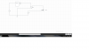
in the first case, i send pulses from arduino with 5v highgt.


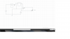
in the second, i use an optocoupler, to send pulses of 12v highgt.


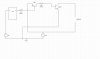
the problem is the following : in both cases, if the load is High, everythings work good. but when i try to increase the load (changing the light dc motor for a 10amperer one), it dosent work. the outpout on the motor pins is 0Volt. i have run a test, and show that if i use a variable load instead of dc motor, the voltage output of the transistor, drops as i rise the load.... why is this happening?? do i need to drive the Base with a lot more Load??? if yes/no, how would i do it??
thanks!
 

Attachments

  • img1.png
    img1.png
    134.2 KB · Views: 826
  • img2.png
    img2.png
    133.3 KB · Views: 834
You need to drive the base with a LOT more current, assuming the TIP35 is as shown in the diagram (motor in the collector) use a PNP driver for it (emitter to 5V, base to uC via a resistor, collector to base of TIP via a resistor) - note that this will invert the PWM, but that's easily corrected in software.

I would suggest though that you first test the TIP by feeding the base directly from 5V via a resistor (no uC), and see how low the resistor needs to be to switch the TIP hard on (or as hard on as you can get).
 
i have tried oparating the TIP35C directly from 5vand 12v, with a 220ohm resistor. at5v the results are the same. but if i wire 12v and 220ohm to base, then it "Works" although i dont know the max ampere it needs...

so you mean i should try something like this?? how much ampere should the PNP transistor be??
 

Attachments

  • img3.jpg
    img3.jpg
    85.8 KB · Views: 1,285
i have tried oparating the TIP35C directly from 5vand 12v, with a 220ohm resistor. at5v the results are the same. but if i wire 12v and 220ohm to base, then it "Works" although i dont know the max ampere it needs...

so you mean i should try something like this?? how much ampere should the PNP transistor be??

No, not like that, the emitter of the PNP MUST go to 5V, not the 12V.

220 ohm is FAR too high, take the resistor to the 5V rail (as I suggested to try earlier), but try a 39 ohm or something in that range (about 100mA drive to the base).

Then with the motor under high load, measure the voltage drop between emitter and collector - the lower the better (should be under 0.5V, and could be down to 0.1V) - try lowering the value of the resistor and see if the voltage drops. Once the transistor is saturated, making the resistor any lower won't drop the voltage any further.
 
couple of questions :)
1) why is it different, if the emiter of the pnp goes to 5v and not the 12v??
2) when you say resistor lower than 220ohm, you mean the resistor R1(PNP;s base) or the R2(TIP35C base). although, as i see it now, the R2 must be as low as possible or else there is no poin in having the PnP transistor in the first place :D
3) when u say 100mA to the base, u mean the PnP's base, or the TIP35C base?? :)
 
1) Because the uC is powered from 5V, if you take the emitter to 12V then the transistor can never be turned OFF.

2) That's correct.

3) The TIP's base - the point is to try and stick enough current in it's base to turn it fully ON.
 
You might try a MOSFET since they are voltage controlled and only require current to charge and discharge the gate capacitance.
 
i didint thought of MOSFET tbh... maybe cause i never really got to use any with succes :D how would i go wiring a MOSFET (and what type) for that work ? :)
 
I suggest that you should try out this TIP35 version (faster switching, lower dissipation).
Logic Level Mosfet (N Channel) is better. :)

Regards,
Csaba
dcmotor.jpg
 
The datasheet for the TIP35 shows that it turns on with a maximum 1.8V loss with a 15A load when its base current is 1.5A. Your base current with the 220 ohm base resistor is only 0.02A.
 
With a base resistor of 10 ohms then the base current is about only 350mA which is not enough to turn on the TIP35 properly. The 10A motor might get only 6v to 9v and the TIP35 will get VERY hot.
 
hFE is used for a linear amplifier with Vce= 4V. The transistor IS NOT SATURATED! You show the "typical" hFE, not the MINIMUM.
The datasheet lists a MAXIMUM saturation voltage drop of 1.8V when the collector current is 15A and the base current is 1.5A.
 
Yes, you're right. It's a typical characteristics at 25 Celsius.
The transistor operates in the linear region end (IB cca. 200mA) in this application.

Regards,
Csaba
tip35.jpg
 
well, i tried with a pnp and 10ohm resistor... still the 35C dosent saturate enough.... i tried 5ohm resistor, that 1ampere is too much for a small resistor >_> . so i guess i am not going to be using the TIP35C since it requires that many amperes to saturate...
i will try going with the mosfet way. but. can i also use, 2 TIP121, to do the same job?? u know, like wired parallel..
 
Status
Not open for further replies.

Latest threads

New Articles From Microcontroller Tips

Back
Top