Continue to Site

Welcome to our site!

Electro Tech is an online community (with over 170,000 members) who enjoy talking about and building electronic circuits, projects and gadgets. To participate you need to register. Registration is free. Click here to register now.

  • Welcome to our site! Electro Tech is an online community (with over 170,000 members) who enjoy talking about and building electronic circuits, projects and gadgets. To participate you need to register. Registration is free. Click here to register now.

I RECALL A THREAD about controlling the LCD brightness

Status
Not open for further replies.
Swordfish has a soft SPI library.. For PWM he will need a library! As he cant install the calculator, internal PWM may be off the table.

I'm not thinking how you or I would do it, That would be simple..
 
I thought Swordfish had all libraries available and easily accessible
I'm not thinking how you or I would do it, That would be simple..
That's a very good point but wouldn't it need the library for the digital pot?

Mike.
 
I thought Swordfish had all libraries available and easily accessible

That's a very good point but wouldn't it need the library for the digital pot?

Mike.
Agreed... Let just let Jon sort it out as usual!
 
will consider the digital pot but at what cost?

The cost of EVERYONE'S sanity.

I explained exactly the steps you need to follow to use PWM, which will require TWO parts at a cost of almost ZERO.

1 – Include the PWM2 module (which I explained where to find).

2 – SetFreq in the PWM2 module. Use the calculator I linked to plug in a realistic value or pull one out of your butt; the PWM2 module will deal.

3 – Set the duty cycle percentage. 0% = 0 volts. 50% = ½ supply voltage, 67% = ⅔ supply voltage. 99% =:supply voltage.

4 – Start PWM.

Geez. It's taken me 10× longer to write this than it would have taken to test it.


A digital pot is not an answer for you. As far as I recall [which believe me, is way too frick'n much], you've never used SPI before. So it's just another layer not to understand.
 
If you only need a single PWM channel then you can use the simpler PWM.bas module, but either one should work.

See https://www.sfcompiler.co.uk/wiki/pmwiki.php?n=SwordfishUser.PWM (for the second time)

It's pretty straight-forward...
Code:
// import PWM module...
Include "PWM.bas"

// local duty cycle as a percent, 0-100...
Dim Duty As Byte

// main program...
SetFreq(5000)
While true
   Duty = 0
   Repeat
      SetDutyPercent(Duty)
      Inc(Duty)
      DelayMS(10)   
   Until Duty > 100
Wend

Single IO pin, no SPI libraries, etc.
 
It's pretty straight-forward...

Am I correct in believing that the pwm module will do its best to deal with any frequency entered?
 
If you call SetFreq() it'll try and figure out the prescaler and settings.
If the function returns true then it was successful. If it returns false then it couldn't calc a setting to match the given freq.

You can use various calculator programs to figure out the settings and set it up yourself too.
The wiki page shows examples using both methods.
 
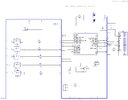
Well hopefully this is correct for the CONTRAST pin/PWM
 

Attachments

  • FAST 5.jpg
    FAST 5.jpg
    416.1 KB · Views: 204
Y'all know you might as well be talking Chinese for all the good your comments will do MrDEB.

The basics. As Nigel said, you need an RC low pass filter. He suggested 1k and 10uF, which gives a cutoff frequency of 15.9 Hz. I might suggest 1k and 1 uF to make the capacitor smaller, which gives a cutoff frequency of 159 Hz.

My 10uF 25V is already tiny, no point making it smaller - it's not as big as the BC337 it sits next to :D
 
From post #15......

geez.jpg
 
I just 'bunged in' what I had - I wanted smooth, and settling time isn't any sort of issue for simply setting the contrast of an LCD - the scope shows how smooth it is (no sign of any ripple), and it works perfectly. My intention was to try different values, but it worked so well that I never bothered.
 
Post #35 wasn't directed at you Nigel Goodwin but rather at MrDEB. If he has taken time to even look at the link, he'd have seen the schematic for the RC filter.
 
well I finally have a picture of the completed sign I made for our town centienial
342083384_977178593609850_1732883053122165851_n.jpg
 
Status
Not open for further replies.

Latest threads

New Articles From Microcontroller Tips

Back
Top