Continue to Site

Welcome to our site!

Electro Tech is an online community (with over 170,000 members) who enjoy talking about and building electronic circuits, projects and gadgets. To participate you need to register. Registration is free. Click here to register now.

  • Welcome to our site! Electro Tech is an online community (with over 170,000 members) who enjoy talking about and building electronic circuits, projects and gadgets. To participate you need to register. Registration is free. Click here to register now.

Inexpensive DC-DC converter/SMPS design idea and suitable topologies

Status
Not open for further replies.
The input range is very large. Why? That makes the design harder.

As does the silly high voltage requirement of 650v :D

Interstingly the Thorn 9000 TV series from 1975 used a unique configuration they called 'Syclops', which used a single transistor for both SMPSU and LOPT.

It also worked from 90V to about 280V, incredible at the time.

 
The input range is very large. Why?
I would guess the inverter is intended for deriving lower voltages from the high voltage traction battery of different EVs ?
 
This is no harder than any universal PC PSU rated from 100V to 250V. Your specs are for step load response matter with ripple current for stability tradeoffs. ! Define specs!!!
 
The input range is very large. Why? That makes the design harder.

Lets think its saparate system for all output.
Yes, Its for battery charger or EV application. To start with a simpliest one take a look at it, its HV pin takes 700V. https://www.ti.com/lit/ds/symlink/ucc28740.pdf?ts=1637161141066&ref_url=https%3A%2F%2Fwww.ti.com%2Fproduct%2FUCC28740%3FkeyMatch%3DUCC28740%26tisearch%3Dsearch-everything%26usecase%3DGPN , it seems like inapropiate for input range.

Right at this moment I am thinking about quasi resonant flyback converter topology.
Take a look here what Infineon expart has made a note, https://www.mouser.com/pdfdocs/2-9.pdf
 
Last edited:
This is no harder than any universal PC PSU rated from 100V to 250V. Your specs are for step load response matter with ripple current for stability tradeoffs. ! Define specs!!!
Like I said, and if you research the the forward converters used in PSU's you'll find a solution or buy it cheaper.
 
You want 160 to 200 watts.
I think you can use almost any 110-220 ac circuit for a start. Increase the voltage on the MOSFETs. Decrease the current some. Change the turn ratio on the transformer. (increase the primary turns) Increase the inductance. It should work.

220vac makes 308vdc Your dc voltage is 650 max. So I think you need 2X the voltage and 1/2 the current on the primary side. Those numbers are crude but will get you close. For a simple flyback you might be up against 1000V MOSFETs. Another option is half bridge where 750 to 800V MOSFETs will be save.

In post #6 you showed some parts used in small power supplies. Go back and look at those thinking 2x voltage and 0.5 current.
Very impressive feedback.
Yes I understand what you mean.
Right at this moment, TI suggest a very easy flyback type, take a look, just need to remove bridge diode, Constant-Voltage, Constant-Current (CVCC) Flyback controller with Secondary Side Regulation (SSR)
Here may be transformer turn can be modify.

Seconly, Infineon suggest a good design, ICE2QS02G
12V.5V and 24V can be set by 950V mosfet, IPD95R450P7 or IPW90R120C3

Kindly review those datasheet and make a decision.
 
All PC PSUs with 3 or more outputs use forward converters because they are better for many reasons; lower impedance, lower cost, more stable over a wider range of loads, and input voltage and only need 1 feedback from the main voltage with tight cross load regulation (low error from high mutual coupling.) as I said look at any design of these type and understand why they can sell for 0.15 cents per watt. You also want to consider active PFC.

but if you don't have good (detailed) design specs, don't expect good results

you will run into problems with light loads on flyback overshoot and sub-switching resonance as well as EMI on max load, if this is your first rodeo.
 
Last edited:
All PC PSUs with 3 or more outputs use forward converters because they are better for many reasons; lower impedance, lower cost, more stable over a wider range of loads, and input voltage and only need 1 feedback from the main voltage with tight cross load regulation (low error from high mutual coupling.) as I said look at any design of these type and understand why they can sell for 0.15 cents per watt. You also want to consider active PFC.

but if you don't have good (detailed) design specs, don't expect good results

you will run into problems with light loads on flyback overshoot and sub-switching resonance as well as EMI on max load, if this is your first rodeo.
Well, lets see if there is anything within this input range.
I dont want to consider for PFC because its DC-DC conversion.
If you look at my #12 response, those IC provides safer application.
 
Well, lets see if there is anything within this input range.
I dont want to consider for PFC because its DC-DC conversion.
If you look at my #12 response, those IC provides safer application.
The DC input has to come from AC for PFC.
I hope you have better specs than 150mVpp steady state unless that is Ok assuming your layout and material choices match theirs and what is the Vo min from a step load?
What is your safety factor spec? Not saying it is a bad design , but without specs how does that stackup to a forward triplet converter. Not as good IMHO.
 
All PC PSUs with 3 or more outputs use forward converters because
No I think not. Forward has more parts.
For small supplies they are mostly flyback. Here at 200 watts, I think Flyback and Forward are about equal.
You also want to consider active PFC.
No
Kindly review those datasheet and make a decision.
This is your job.
You could look for reference designs. Look for 200 watt isolated power supplies.

Here is an example. TI You will need to remove the PFC part of the design. I think it is only 150 watt.

You could make a 24V supply and then add a small 24 to 12 buck and a small 24 to 5 buck supplies. The two buck supplies are very simple.
 
Last edited:
YOu want simple or best specs? (TBD undefined)

Sure, Forward converters have more parts ( cheap ones) but far better stability and lower error voltage by at least 1 order of magnitude. As far as parts, you can buy 1 part cheaper than re-inventing the wheel and make or buy one medically safe. https://www.smpspowersupply.com/atx-power-supply-pfc-schematic.pdf The leakage current in the Pi filter can be eliminated below safe limits with enough stage CM filters.


The quality of the magnetics is your choice but critical and defined by excellent specs.
 
Last edited:
YOu want simple or best specs?
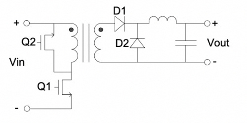
He needs simple. This project is too much for the first one. It is way beyond his skill set. One option is this circuit to make 24V and then add two simple buck circuits to get 12 and 5.
1637258696403.png
1637259108833.png
1637259114319.png

Hi Tony, If you want to teach him how the below circuit works go ahead. Neither of us are getting paid to teach today. Choose a simple option.
1637258804571.png
 
Status
Not open for further replies.

New Articles From Microcontroller Tips

Back
Top