Hellmut1956
Member
Dear friends. Allow me to start warning you that same as I love to read threads were things are explained in detail, my own style is very lengthy. As I have serious trouble with my health, reports I do write in threads also have the purpose to bring me up to speed when I have interrupted my activities around any certain topics.
I have been since early in my life a fan of science fiction and so my goal was to study space and aeronautical engineering in Germany. I only pursued this study for 4 semesters, as pretty soon I realized that the main difference between designing and building a rocket to a washing machine was that the manufacturing tolerances were tighter with rockets and also the material used more expensive. So I did find myself at the university between students that have passed their live as kids working on their cars and motorcycles. Luckily I found a job while studying with a german steel company building container handling equipment and i got the charter to translate all their documentation to spanish and work as a translator when the company head to do with spanish speaking people. In that time, as laziness has always the engine driving my creative thinking I did develop a system to support the translation process. The supplier failed and so I had to get into the electronics subjects related to that project to educate my lawyer so that I could win the process. This way I fall in love with electronics in general and with graphic processors and controller. The outcome was that National Semiconductors in Germany hired me as a "Field Application Engineer" in short "FAE" and this was the beginning of a decade long career in the Semiconductor and Telecommunication industry. Her a picture of the first evaluation kit National created to support their DP8500 product family. One of the key marketing managers, I have kept a friendship with him until still today due to our common love for flying single engine motor planes:
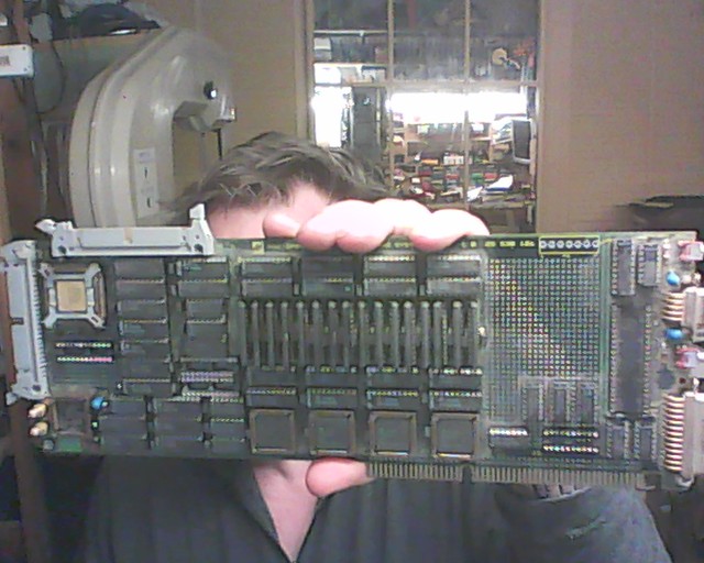
This board had a "ENGR-SAMPLE" of the DP8500 so i do have a special affinity with it. This was in 1986, when national with its DP8500 and TI with its 34010 were the first 2 companies to offer processor based graphic engines opposed to the mainstream still using graphic controllers like the then famous NEC7220.
When the Internet bubble burst in 2000/2001 I lost my job as a Business Development Director at Lucent, a spin-off from ATT and then one of the largest suppliers of equipments and services for telecommunication providers. After realizing that I would never again find a job to be hired for, in Germany the age of 45 was impediment, i did reactivate my old hobby from y days as a kid, building models. As I had to care about spending as little as possible money for my hobby I decided to switch from airplanes to naval models and there to sailboats. So I did purchase a plan of a long keel body sailboat and started to build it. After some time I started to focus my efforts towards developing my own solutions for electronics in the sailboat.
Over many years i did start to work on building myself a workshop and get order into the many things I did have in inventory. Luck of enough financial resources I had to switch from buying a part I knew I already had to get order into the stuff that had accumulated over decades.
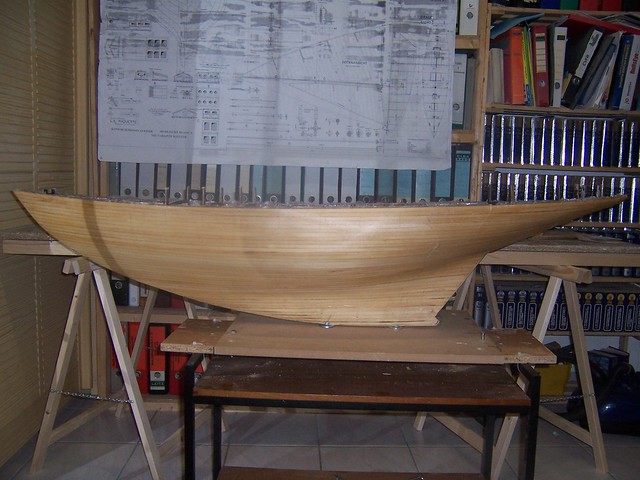
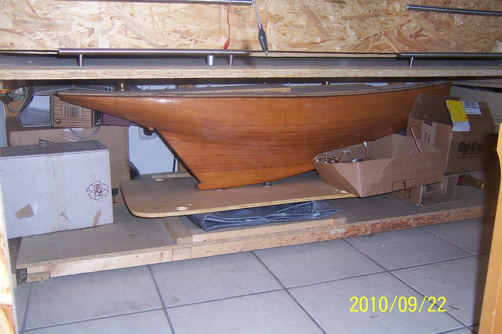
Here a few photos to entertain you and to make the reading of this thread easier. Here a view of the body of my sailboat. Working with wood is a very sensual work as wood feels nice and moving your hands over the surface of the body shown here is pleasant.
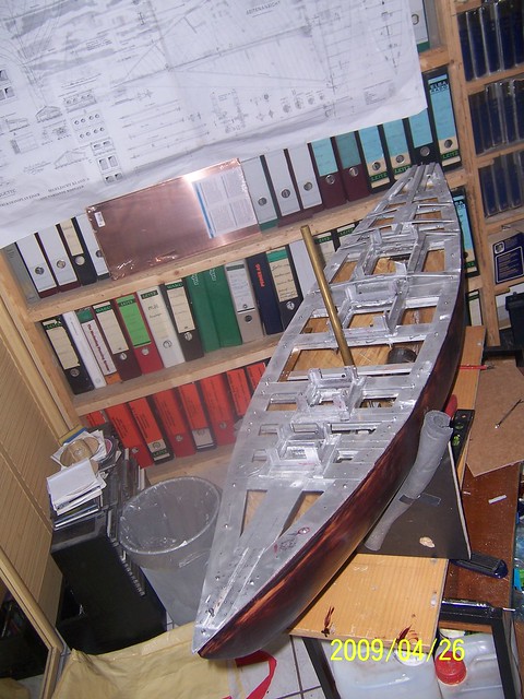
As one of the purposes in working on this model was learning about the technologies I was encountering in this process, first wood as shown in the previous image, then plastics while working with fiberglass and epoxy to working with aluminium which I did use to build a deck completely detachable from the wooden body of the sailboat and brass. I will not go into the countless issues that fascinated me as this is outside the scope of the community.
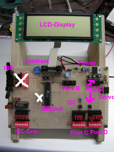
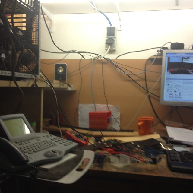
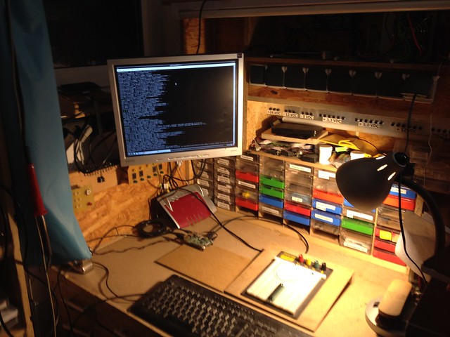
While talking to a fellow aficionado about using our own electronics and to digitize the PWM signal coming out of the R/C receiver we succeeded to have the 8 PWMs coming out of the 8 channels of our R/C receiver to be digitized and displayed on a screen like the one shown in the above picture. We were surprised about how easy this was to be accomplished and what endless opportunities this offered for naval modelers to implement proprietary functionalities in their models. My friend did develop and publish a course that taught naval modelers how to read a schematic and implement it of something he called "Experimental Board" that consisted of short and simple steps which resulted in the feeling of accomplishment by those building it. Naval modelers are intimidated when it is about electronics. Along with it the students were given small programs to verify the implementation after each step of building the hardware. The compiler we used and recommended was "BASCOM". A basic compiler with an extensive library that made instructions available to implement what we called the "building blocks" which recombined would enable the naval modeler to realise most of the functionality he might be interested to do. Kind of a "Lego system".
In those days neither Arduino nor Raspberry Pis did exist and our process used AVR controllers from Avnet, mainly the mega8. In our experimental board we had the students to implement the circuitry connecting the devices using colored cable to be ironed. This procedure was intentional as it forced the student to learn to read the simple schematic and connect the pins using colored wires on the rear side of the board. While this also teaches about how to debug a circuit, remember each individual step was just a small addition to the circuitry, so while it teaches how to debug, how to do the implementation methodological so that errors could be found easily and learn what was the reason for those errors! using a pre-build board that just has to be populated does not offer this learning opportunity and promotes to see electronics as a black box.
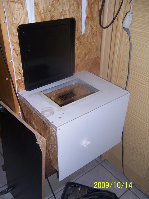
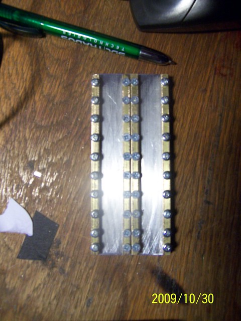
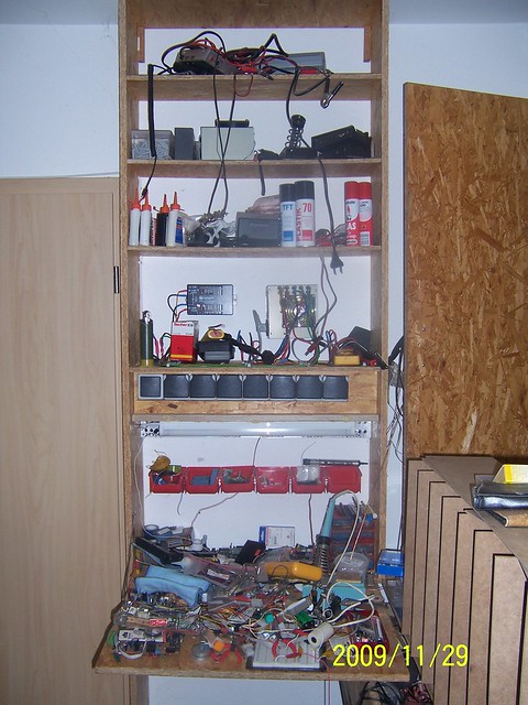
So while for the experimental board ironing of wires was the way to proceed, for my own electronics i wanted to be able to make my own boards. So using a facial UV device used to get brown skin, just 20 USDs at ebay I build a device to have the image of the circuit surface printed with my canon Inkjet printer using overhead transparency foils I could pass the image to a photo sensitive surface of a raw board. In this picture you see the device I bould with a foil having the images of a bunch of boards to take SMD LEDs!
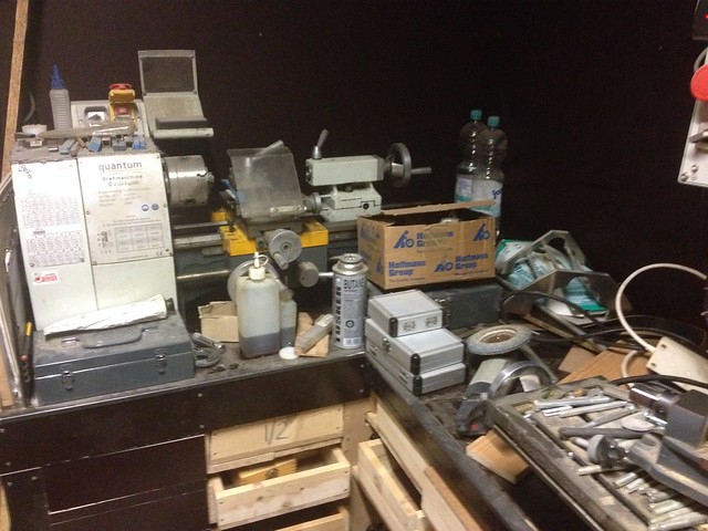
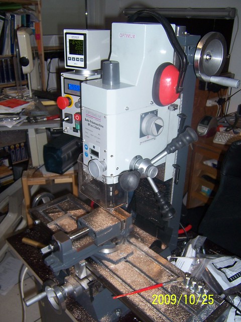
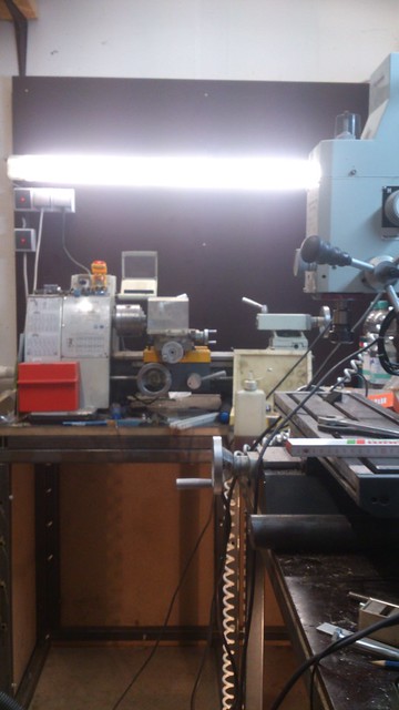
As I will be using a great number of this LEDs in my model i had to build a device which would enable me to build identical boards and to be able to build more of such boards in the future. The requirement to place the holes at their exact defined locations prove to overstress the equipment I used until then. So I decided to my a mill shown on this picture:
This peace of equipment came at a time when the additional possibilities it offered allowed me to get even more ambitious.
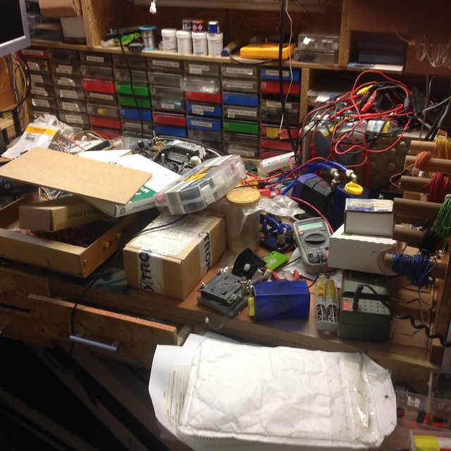
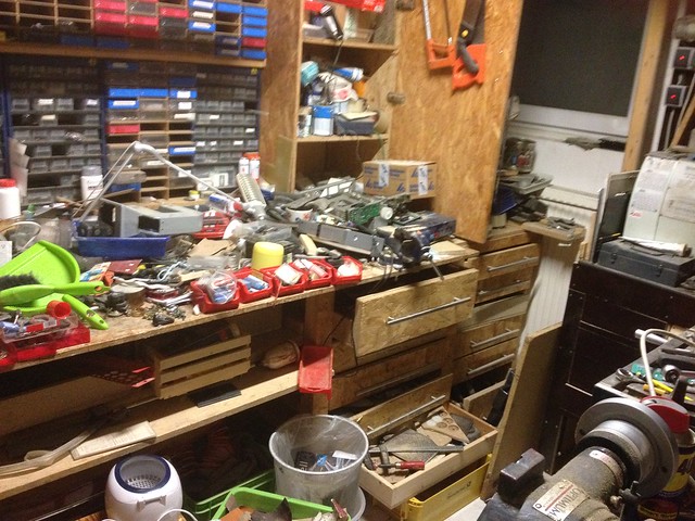
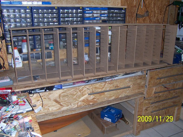
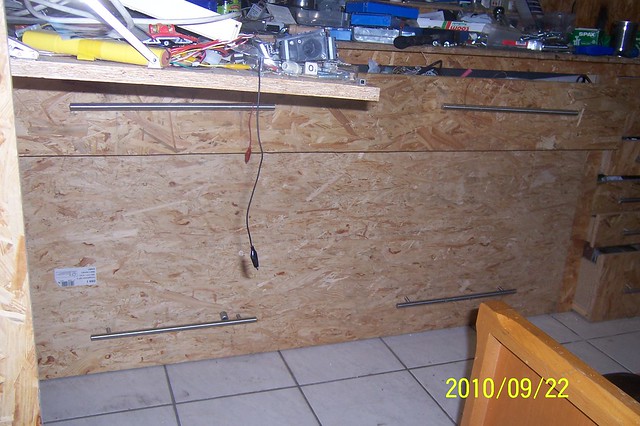
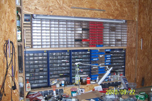
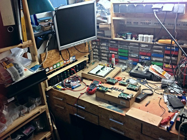
Now I decided to update my workbench to be able to take a huge number of sortiment boxes so that I could start to place the endless number of devices I had laying around!
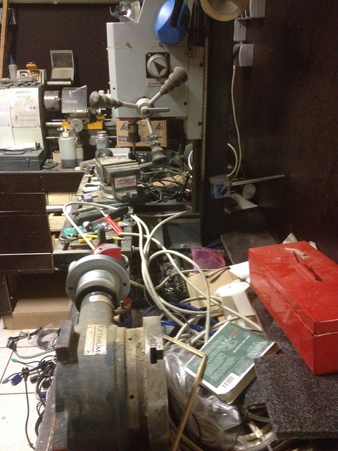
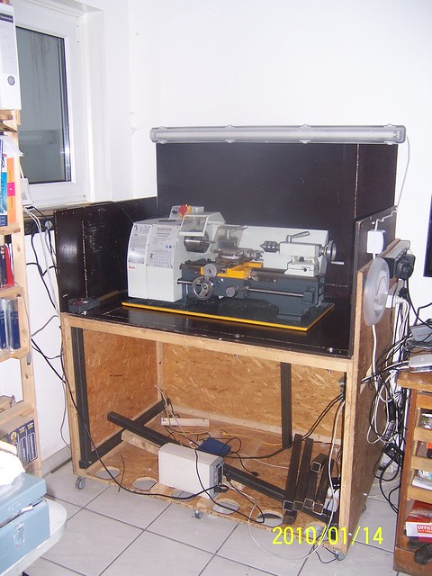
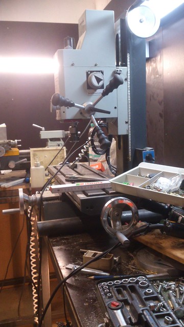
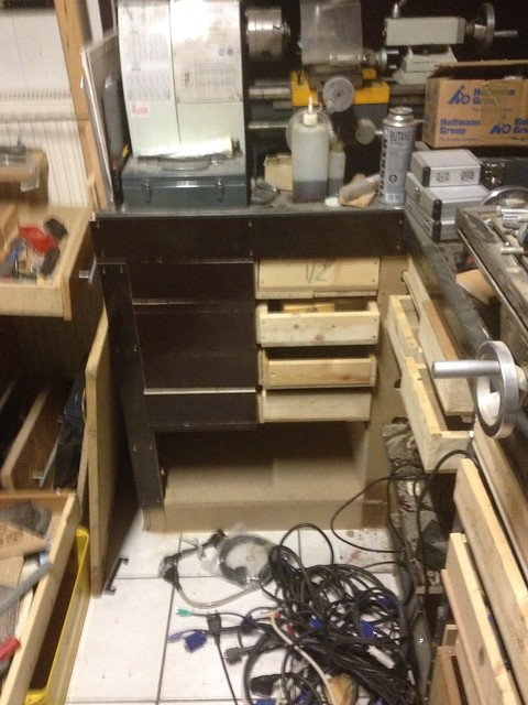
So the next mayor piece of equipment I did purchase was a lathe:
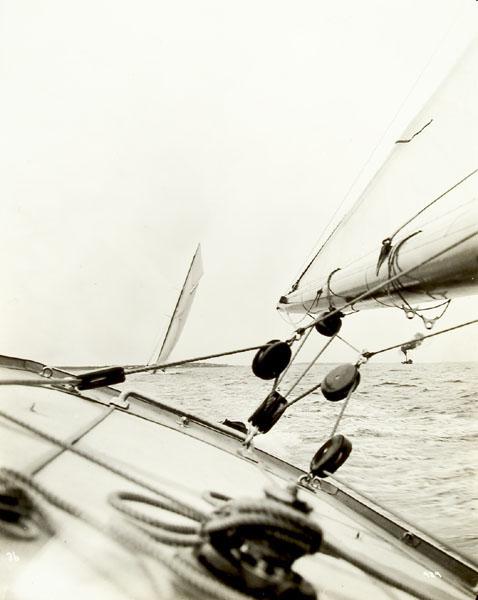
So by now I was able to take a picture as to how my sailboat would look like when finished:

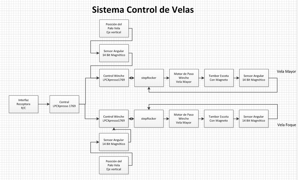
Vaving pursued diverse approaches I did decide to use a stepper motor to implement the winch functionality within my sailboat. I have the plan to use to 8 NM torque stepper motors and I had no clue for how long I could operate this. my goal became to achieve the maximum possible operating time. Doing experiments with the stepper motor and a very advanced stepper motor controller from a german company based in Hamburg, a board called "stepRocker".
To my own surprise during the recording of the video published on YouTube the Stepper Motor achieved dramatically higher step rates that I had assumed in my most wishful thinking. But just see for yourself!
I remember a response I got many years ago from a spanish speaking electronics forum where I published what I called an advanced stepper motor tutorial! As you can hear in the above video I am a very untalented speaker, so the tutorial referenced pictures and graphics which to use I was authorized by the Trinamic head of marketing. This gentleman wrote that he knew stepper motors as the devices that get very hot, he had burned his arm more then once! The reason for this excessive heating of a stepper motor is due to the fact that simple controllers are connected to devices that offer at least the maximum torque required plus some safety margin and are constantly fed with the current required for a specific stepper motor to achieve this torque rating! The pair of L297/L298 are good examples of this traditional stepper motor controllers. Another mayor performance limiting factor in stepper motors is due to instabilities and resonances.
The step rates I do show in the above video was demonstrated using the 24 VDC power coming from a modified PC power supply. In my sailboat I will use 12 cells LiFePO4 batteries with 16Ah of capacity each. When the battery pack is discharged to the point it has to be recharged the voltage supplied will be 24 VDC, when the Pack is full I do get nearly 40 VDC. If you consider that the video shows one of the motors to be used as winches in my sailboat with just 24 VDC, here showed to be dropping from 25.1 VDC to below 25 VDC and the current consumption just before the motors stops just being 1.1 A, while the motor can handle up to 2.8 A! It is important to realize that stepper motors do generate an induced voltage of opposite polarity reducing the effectively available voltage, than you have one of the reasons why a stepper motor is good and efficient at low step rates. The induced voltage has a low value so the effective voltage generating the torque is the applied voltage when the stepper motor is standing still! The higher stepping rate, the higher the absolute value of the induced voltage and the less the torque available. So the video shows the stepping rate of the stepper motor at no load and a bit more than 1/3 of the maximum current allowed! I do plan to experiment with a newer version of the Trinamic stepper technology:
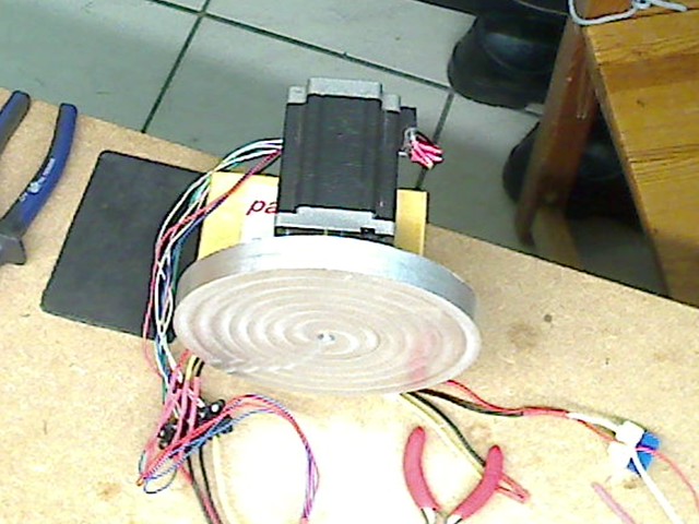
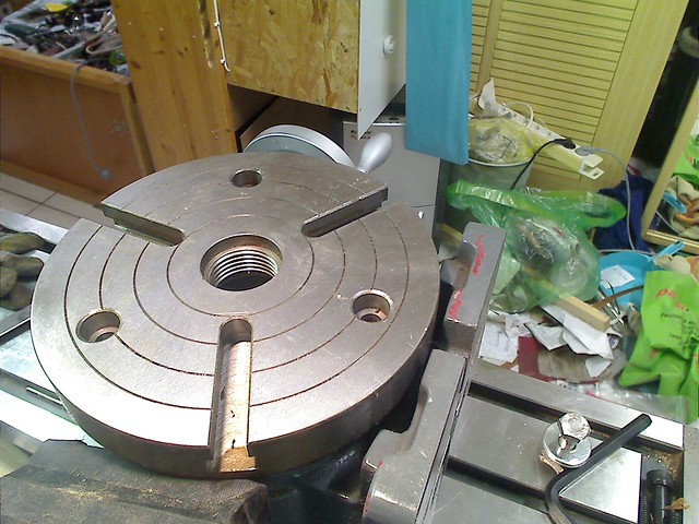
Here a picture of the sheet drum I plan to use. Together with the stepper motor and the control circuitry it makes up the winch. I had to stop my work on the drum as my milling machine got damaged. I did use a rotating table mounted on the coordinate table of my mill to mill this raw version of one of the 2 drums I will have in my sailboat! here a picture of the rotating table mounted on the coordinate table of my mill:
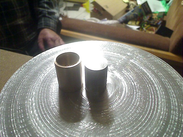
The next picture shows the side of the drum that will be connected to the stepper motor!
Next the picture of the next generation stepper motor evaluation kit from Trinamic:
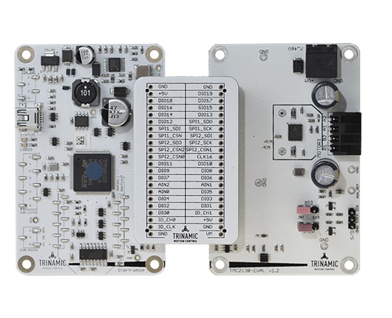
Great about this evaluation kit is that it allows to look into the operation of its TMC2130 stepper motor controller. The right board contains exclusively the TMC2130 and it can be operated with supply voltages up to 60 VDC! The left board is the containing an ARM Cortex controler with the firmware that allows to control the kit via the Trinamic IDE downloadable for free from Trinamic and the source code of the firmware is available. It communicates with the controller via the ARM Cortex CMSIS API, what makes it relatively simple to migrate this software to another ARM Cortex M controller that offers all the peripherals required! The middle board makes all the signals between the two board accessible, so that i.e. they can be viewed and analyzed using logic analyzer i.e.!
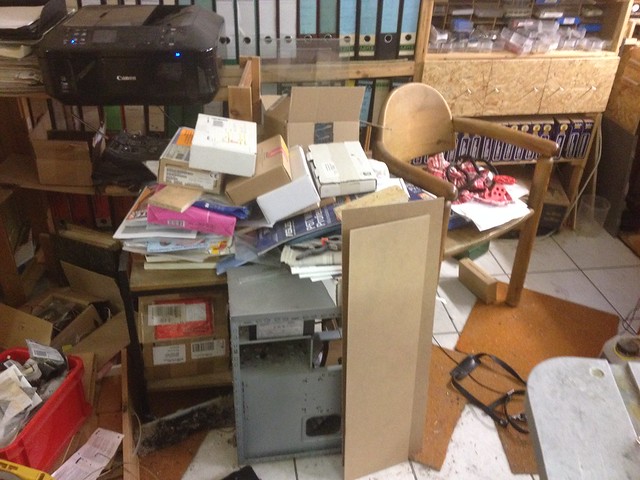
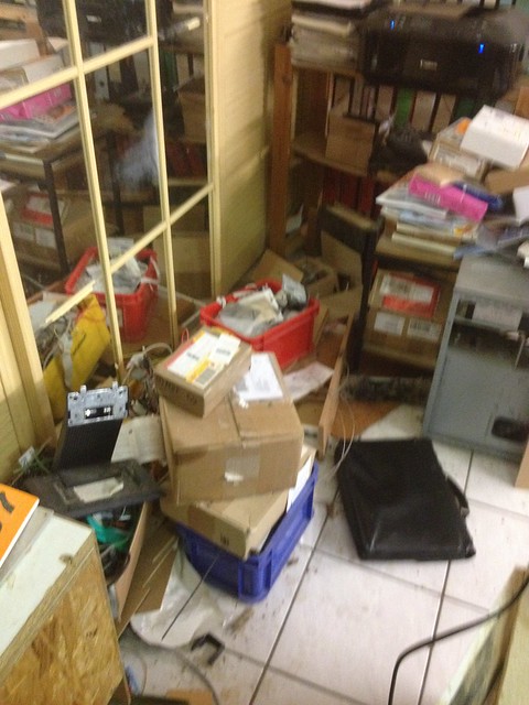
All of this made it evident that I needed further upgrading my workshop!
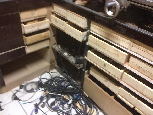
First, with the help of a good friend while I was recovering from my first stroke, we separated as much as possible the dirty work function is my workshop in one area of it and we build a second workbench!
This picture shows that area of my second workbench with the lathe!
I have been since early in my life a fan of science fiction and so my goal was to study space and aeronautical engineering in Germany. I only pursued this study for 4 semesters, as pretty soon I realized that the main difference between designing and building a rocket to a washing machine was that the manufacturing tolerances were tighter with rockets and also the material used more expensive. So I did find myself at the university between students that have passed their live as kids working on their cars and motorcycles. Luckily I found a job while studying with a german steel company building container handling equipment and i got the charter to translate all their documentation to spanish and work as a translator when the company head to do with spanish speaking people. In that time, as laziness has always the engine driving my creative thinking I did develop a system to support the translation process. The supplier failed and so I had to get into the electronics subjects related to that project to educate my lawyer so that I could win the process. This way I fall in love with electronics in general and with graphic processors and controller. The outcome was that National Semiconductors in Germany hired me as a "Field Application Engineer" in short "FAE" and this was the beginning of a decade long career in the Semiconductor and Telecommunication industry. Her a picture of the first evaluation kit National created to support their DP8500 product family. One of the key marketing managers, I have kept a friendship with him until still today due to our common love for flying single engine motor planes:
This board had a "ENGR-SAMPLE" of the DP8500 so i do have a special affinity with it. This was in 1986, when national with its DP8500 and TI with its 34010 were the first 2 companies to offer processor based graphic engines opposed to the mainstream still using graphic controllers like the then famous NEC7220.
When the Internet bubble burst in 2000/2001 I lost my job as a Business Development Director at Lucent, a spin-off from ATT and then one of the largest suppliers of equipments and services for telecommunication providers. After realizing that I would never again find a job to be hired for, in Germany the age of 45 was impediment, i did reactivate my old hobby from y days as a kid, building models. As I had to care about spending as little as possible money for my hobby I decided to switch from airplanes to naval models and there to sailboats. So I did purchase a plan of a long keel body sailboat and started to build it. After some time I started to focus my efforts towards developing my own solutions for electronics in the sailboat.
Over many years i did start to work on building myself a workshop and get order into the many things I did have in inventory. Luck of enough financial resources I had to switch from buying a part I knew I already had to get order into the stuff that had accumulated over decades.
Here a few photos to entertain you and to make the reading of this thread easier. Here a view of the body of my sailboat. Working with wood is a very sensual work as wood feels nice and moving your hands over the surface of the body shown here is pleasant.
As one of the purposes in working on this model was learning about the technologies I was encountering in this process, first wood as shown in the previous image, then plastics while working with fiberglass and epoxy to working with aluminium which I did use to build a deck completely detachable from the wooden body of the sailboat and brass. I will not go into the countless issues that fascinated me as this is outside the scope of the community.
While talking to a fellow aficionado about using our own electronics and to digitize the PWM signal coming out of the R/C receiver we succeeded to have the 8 PWMs coming out of the 8 channels of our R/C receiver to be digitized and displayed on a screen like the one shown in the above picture. We were surprised about how easy this was to be accomplished and what endless opportunities this offered for naval modelers to implement proprietary functionalities in their models. My friend did develop and publish a course that taught naval modelers how to read a schematic and implement it of something he called "Experimental Board" that consisted of short and simple steps which resulted in the feeling of accomplishment by those building it. Naval modelers are intimidated when it is about electronics. Along with it the students were given small programs to verify the implementation after each step of building the hardware. The compiler we used and recommended was "BASCOM". A basic compiler with an extensive library that made instructions available to implement what we called the "building blocks" which recombined would enable the naval modeler to realise most of the functionality he might be interested to do. Kind of a "Lego system".
In those days neither Arduino nor Raspberry Pis did exist and our process used AVR controllers from Avnet, mainly the mega8. In our experimental board we had the students to implement the circuitry connecting the devices using colored cable to be ironed. This procedure was intentional as it forced the student to learn to read the simple schematic and connect the pins using colored wires on the rear side of the board. While this also teaches about how to debug a circuit, remember each individual step was just a small addition to the circuitry, so while it teaches how to debug, how to do the implementation methodological so that errors could be found easily and learn what was the reason for those errors! using a pre-build board that just has to be populated does not offer this learning opportunity and promotes to see electronics as a black box.
So while for the experimental board ironing of wires was the way to proceed, for my own electronics i wanted to be able to make my own boards. So using a facial UV device used to get brown skin, just 20 USDs at ebay I build a device to have the image of the circuit surface printed with my canon Inkjet printer using overhead transparency foils I could pass the image to a photo sensitive surface of a raw board. In this picture you see the device I bould with a foil having the images of a bunch of boards to take SMD LEDs!
As I will be using a great number of this LEDs in my model i had to build a device which would enable me to build identical boards and to be able to build more of such boards in the future. The requirement to place the holes at their exact defined locations prove to overstress the equipment I used until then. So I decided to my a mill shown on this picture:
This peace of equipment came at a time when the additional possibilities it offered allowed me to get even more ambitious.
Now I decided to update my workbench to be able to take a huge number of sortiment boxes so that I could start to place the endless number of devices I had laying around!
So the next mayor piece of equipment I did purchase was a lathe:
So by now I was able to take a picture as to how my sailboat would look like when finished:
Vaving pursued diverse approaches I did decide to use a stepper motor to implement the winch functionality within my sailboat. I have the plan to use to 8 NM torque stepper motors and I had no clue for how long I could operate this. my goal became to achieve the maximum possible operating time. Doing experiments with the stepper motor and a very advanced stepper motor controller from a german company based in Hamburg, a board called "stepRocker".
To my own surprise during the recording of the video published on YouTube the Stepper Motor achieved dramatically higher step rates that I had assumed in my most wishful thinking. But just see for yourself!
I remember a response I got many years ago from a spanish speaking electronics forum where I published what I called an advanced stepper motor tutorial! As you can hear in the above video I am a very untalented speaker, so the tutorial referenced pictures and graphics which to use I was authorized by the Trinamic head of marketing. This gentleman wrote that he knew stepper motors as the devices that get very hot, he had burned his arm more then once! The reason for this excessive heating of a stepper motor is due to the fact that simple controllers are connected to devices that offer at least the maximum torque required plus some safety margin and are constantly fed with the current required for a specific stepper motor to achieve this torque rating! The pair of L297/L298 are good examples of this traditional stepper motor controllers. Another mayor performance limiting factor in stepper motors is due to instabilities and resonances.
The step rates I do show in the above video was demonstrated using the 24 VDC power coming from a modified PC power supply. In my sailboat I will use 12 cells LiFePO4 batteries with 16Ah of capacity each. When the battery pack is discharged to the point it has to be recharged the voltage supplied will be 24 VDC, when the Pack is full I do get nearly 40 VDC. If you consider that the video shows one of the motors to be used as winches in my sailboat with just 24 VDC, here showed to be dropping from 25.1 VDC to below 25 VDC and the current consumption just before the motors stops just being 1.1 A, while the motor can handle up to 2.8 A! It is important to realize that stepper motors do generate an induced voltage of opposite polarity reducing the effectively available voltage, than you have one of the reasons why a stepper motor is good and efficient at low step rates. The induced voltage has a low value so the effective voltage generating the torque is the applied voltage when the stepper motor is standing still! The higher stepping rate, the higher the absolute value of the induced voltage and the less the torque available. So the video shows the stepping rate of the stepper motor at no load and a bit more than 1/3 of the maximum current allowed! I do plan to experiment with a newer version of the Trinamic stepper technology:
Here a picture of the sheet drum I plan to use. Together with the stepper motor and the control circuitry it makes up the winch. I had to stop my work on the drum as my milling machine got damaged. I did use a rotating table mounted on the coordinate table of my mill to mill this raw version of one of the 2 drums I will have in my sailboat! here a picture of the rotating table mounted on the coordinate table of my mill:
The next picture shows the side of the drum that will be connected to the stepper motor!
Next the picture of the next generation stepper motor evaluation kit from Trinamic:
Great about this evaluation kit is that it allows to look into the operation of its TMC2130 stepper motor controller. The right board contains exclusively the TMC2130 and it can be operated with supply voltages up to 60 VDC! The left board is the containing an ARM Cortex controler with the firmware that allows to control the kit via the Trinamic IDE downloadable for free from Trinamic and the source code of the firmware is available. It communicates with the controller via the ARM Cortex CMSIS API, what makes it relatively simple to migrate this software to another ARM Cortex M controller that offers all the peripherals required! The middle board makes all the signals between the two board accessible, so that i.e. they can be viewed and analyzed using logic analyzer i.e.!
All of this made it evident that I needed further upgrading my workshop!
First, with the help of a good friend while I was recovering from my first stroke, we separated as much as possible the dirty work function is my workshop in one area of it and we build a second workbench!
This picture shows that area of my second workbench with the lathe!

")