Electro Tech is an online community (with over 170,000 members) who enjoy talking about and building electronic circuits, projects and gadgets. To participate you need to register. Registration is free. Click here to register now.
Welcome to our site! Electro Tech is an online community (with over 170,000 members) who enjoy talking about and building electronic circuits, projects and gadgets. To participate you need to register. Registration is free. Click here to register now.
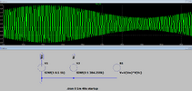
Taking a look at your .asc you have a 1kHz signal linearly added to a 384.259 Hz carrier. You better have a really long antenna for that puppy
If you are thinking of AM, then you should use a controlled voltage for the carrier, multiplying it by the value of the modulating signal, and taking a 50% DC offset. As a suggestion probe the signal source, I don't think it's what you expect.
I cheated and swiped the ideas from http://www.auldies.euweb.cz/me/Amf1.html
because I couldn't work out how to do AM either It looks OK at 100%, though aliasing makes it still a bit grotty. But AM it is.
The linked website indicates that this is an RF preamplifier for a range of 20kHz to 30MHz. 1 kHz is way too low a frequency.
Also, you do require to tune the input tank circuit to the input frequency.
And, run the DC bias operating point before doing a transient analysis. As mentioned in the article, you should adjust the bias resistors to have an idling VDS and VCE value of half the supply.
Lastly, simplify your circuit. You don’t require ancillary components like D1 to run your simulation.
I kinda assumed the OP's comment in the .asc faint 1KHz signal on faint 384KHz station.
implied they were aiming for a 384kHz carrier. Which is odd in itself, as it's not broadcast and not ham, are they into NDBs?
Agreed, a .sweep to tune it would be in order. At the moment it's fed from a very low impedance voltage source, so that first tuned circuit ain't gonna tune anything in the face of such a stiff source. A electrically short antenna would usually be expected to have quite a high impedance, so a nod to that would improve the simulation, 100k would ab a good start. But the OP needs to clarify a bit more what he's trying to do
This site uses cookies to help personalise content, tailor your experience and to keep you logged in if you register.
By continuing to use this site, you are consenting to our use of cookies.

")