Electro Tech is an online community (with over 170,000 members) who enjoy talking about and building electronic circuits, projects and gadgets. To participate you need to register. Registration is free. Click here to register now.
Welcome to our site! Electro Tech is an online community (with over 170,000 members) who enjoy talking about and building electronic circuits, projects and gadgets. To participate you need to register. Registration is free. Click here to register now.
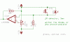
I found this circuit on NET. I want to ask that this circuit will work for both IR Light and LASER.
And another thing i am replacing +12 Volts with +5 Volts.........and - 12 Volts with 0 Volt(GND).
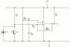
A reverse-biased photo-diode is a lot less sensitive than a photo-transistor.
The 5.6k resistor should be a much higher value for the photo-diode to have some sensitivity.
The photo-transistor will have voltage gain if it is common-emitter instead of the emitter-follower.
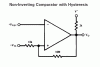
The comparator should have hysteresis so that it doesn't oscillate, amplify its own noise or amplify noise from the power supply.
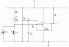
It is good that you added hysteresis.
The output will be low when there is enough light.
The photo-detector is DC-coupled to the comparator so it might not work when there is high ambient light. IR receiver ICs have the photo-detector AC-coupled with a capacitor so they continue to work during high ambient light.
IR receiver ICs also have a bandpass filter that blocks interference from mains-powered lights, and the light beam is modulated at the tuned frequency.
R2 is a very low value. So the light must be fairly bright to make the phototransistor conduct enough, and the light must be extremely bright to make the photo-diode conduct enough. A reflection won't be bright enough so use 10k, 100k or 1M for R2.
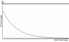
Suppose our phototransitor is under constant light source if it will be AC coupled then it's output will be droped after few moments as shown in picture (because of capacitor fully charged).
output low means there is no light on the photosensor but the photosensor is under constant light source.
Hope u understand. my poor English.
This site uses cookies to help personalise content, tailor your experience and to keep you logged in if you register.
By continuing to use this site, you are consenting to our use of cookies.