Continue to Site

Welcome to our site!

Electro Tech is an online community (with over 170,000 members) who enjoy talking about and building electronic circuits, projects and gadgets. To participate you need to register. Registration is free. Click here to register now.

  • Welcome to our site! Electro Tech is an online community (with over 170,000 members) who enjoy talking about and building electronic circuits, projects and gadgets. To participate you need to register. Registration is free. Click here to register now.

LC Circuit at Amp's output

Status
Not open for further replies.

EngIntoHW

Member
Hi,

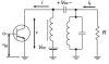
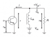
I read that because of the class A amplifier nonlinearities, it is necessary to connect a parallel LC circuit with resonant frequency equal to the operating frequency to suppress any possible harmonic components.

Could someone explain please how it supresses harmonic components?

Thanks.

ce_amp-png.57883
 

Attachments

  • CE_Amp.png
    CE_Amp.png
    7 KB · Views: 321
Hello,

Without seeing more of the circuit, the parallel LC works by presenting a relatively high impedance to the output for frequencies near the resonant frequency, and by presenting a relatively low impedance for other frequencies. In this way the unwanted frequencies are dissipated while the good frequency passes. The drawback would be it would need tuning if you change the output frequency.
 
Hi,

I have an additional question please.
How do you see it that the LC circuit is connected in parallel to the amplifier / load?
 
I read that because of the class A amplifier nonlinearities
And non-linearity in any other class of amplifier will cause harmonics.

Could someone explain please how it supresses harmonic components?
As drawn I dont think that it would do anything for harmonic supression.
The inductor (Lch) provides a high impedance at the operating frequency and a low resistance for the collector supply.
The capacitor (Cb) couples the output from the collector into the load (R).

The maximum output power from this circuit will be W = (R x Vcc/4).

To suppress the harmonics, depending on the application, you could use a proper parallel tuned circuit, or a low-pass filter. As per the attachments.

JimB
 

Attachments

  • LC and filter.PNG
    LC and filter.PNG
    12.2 KB · Views: 155
Hi,


I assumed that the circuit was not drawn correctly and that the question body was more accurate or R was not the load. If that's not the case however, then we would have to look at this again.

The inductor would shunt lower frequencies and allow higher frequencies to pass through, and same with the cap, so if R is the load then we have a slightly different story here. It starts to look more like a high pass filter.
 
Last edited:
The inductor would shunt lower frequencies and allow higher frequencies to pass through, and same with the cap, so if R is the load then we have a slightly different story here. It starts to look more like a high pass filter.
I agree with that.

JimB
 
Hi,

First of all, thank you very much ! :)

I understand what you said that it is an high pass filter.
Wasn't it enough to use only the capacitor or only the inductor, to make an HPF?

Would you say that the following circuit makes a parallel LC circuit with a load R?

lc_circuit-jpg.57946
 

Attachments

  • LC_Circuit.jpg
    LC_Circuit.jpg
    17.3 KB · Views: 277
Last edited:
Hi,

Yes that is what i was talking about originally. The second L and C in that new schematic.
 
Hi,

Using one or the other you get a first order response, using both you get a second order response (if done right of course), so that would mean a sharper response.

It also helps to look at the application, what they are trying to do here. It could be an outright mistake.
 
Last edited:
Hi,

First of all, thank you very much ! :)

I understand what you said that it is an high pass filter.
Wasn't it enough to use only the capacitor or only the inductor, to make an HPF?

No, because it's not a high pass filter, it's a tuned circuit RF amplifier - well it's not actually, it's only a crude partial representation of one in the 'intended to confuse' text book style.
 
Hi,


Since the values of the components were not given i was free to choose what values i wanted. Choosing several different values, i got a simulation that showed low amplitude for low frequencies, higher amplitude for higher frequencies, which of course equates to a high pass.

If the values are chosen appropriately i suppose it would be possible to chose an inductor that resonated with the transistor capacitance, but then i would expect to see some kind of tuning adjustment present too.
Alternately, if in the application the transistor limits the high frequency response then we can say we have a sort of bandpass response.
That's why i suggested that we know what the application is and what the values were.

Inductors are also used in collector circuits to help decouple the AC from the power supply. They allow the DC bias but dont allow the AC to get through too much.
 
Last edited:
Thank you very much guys.

I'm continuing reading the book that discuess power amplifier.
if you're interested, it is called Switchmode RF Power Amplifiers (Andrei Grebennikov & Nathan O. Sokal).

I encountered the circuit below and have a question.

The parallel LC resonator tuned to 3fo, passes only frequency 3fo?

Thank you again mates.

lc-jpg.57995
 

Attachments

  • LC.jpg
    LC.jpg
    19 KB · Views: 259
Hi Eric,
Thanks.

I understand that summing all odd harmonics results with a square wave.

I'm trying to figure out how the below circuit sums them up - in this case the 1st, 3rd and 5th harmonics.

lc-jpg.57995
 
Last edited:
Parallel tuned circuits present a high impedance at their resonant frequency.

Series tuned circuits present a low impedance at their resonant frequency.

The example circuit which you are showing will have maximum output at Fo.
At 3Fo and 5Fo, the harmonic components of the signal will be attenuated.

The circuit as drawn is an AC equivalent circuit which is not a practical circuit, it omits DC supply and bias circuits.

JimB
 
Hi Eric,
Thanks.

I understand that summing all odd harmonics results with a square wave.

I'm trying to figure out how the below circuit sums them up - in this case the 1st, 3rd and 5th harmonics.

lc-jpg.57995

Hi,

That circuit is a rough diagram of what it might take to reduce the square wave harmonics to get a more pure sine fundamental output. It roughly gets rid of the 3rd and 5th harmonics, which are the most important harmonics in the square wave to get rid of if you want a more perfect pure sine output at the fundamental frequency. So in the square wave we have a bunch of added harmonics, and in that filter we subtract some amount of both the 3rd and 5th harmonics in an attempt to get rid of them and get a better pure sine wave.
The last filter shown knocks down more harmonics because it's resonant at the fundamental frequency f0 but this filter unlike the other two is in parallel which means it lets the fundamental pass and shunts part of the other frequencies. The two in series block those respective frequencies and let some of the other ones pass, like the fundamental.
 
Last edited:
Status
Not open for further replies.

Latest threads

New Articles From Microcontroller Tips

Back
Top