Electro Tech is an online community (with over 170,000 members) who enjoy talking about and building electronic circuits, projects and gadgets. To participate you need to register. Registration is free. Click here to register now.
Welcome to our site! Electro Tech is an online community (with over 170,000 members) who enjoy talking about and building electronic circuits, projects and gadgets. To participate you need to register. Registration is free. Click here to register now.
What if you added a resistor between the transistor and ground the same size as the pull up?
I think you also need a current limiter in series with the LED
All of the resistors will act as current limiters. If the transistor is supposed to represent a LM393 output, there isn't access between the transistor and ground. If it was a standard transistor output then there would be access. But you have given a possible solution for the LM393 output. Just put the resistor between the led and the collector. The pull-up resistor would actually be two resistors of the same size with the led connected in the middle.
I'm going to have to look at the 3 pin circuit. At first glance it looks like D2 and D1 will be on but at half brightness. I need to look at the turn on points for each of the diodes and Vce of Q1. I don't recall what voltage Q1 collector is at when turned on.
Yes, but then the current through D2 would be drastically reduced and you would have to increase the supply volts above 5V. D2 current is already slightly lower than for D1.
Why would you want to use a zener when an ordinary diode does the job?
Yes, but then the current through D2 would be drastically reduced and you would have to increase the supply volts above 5V. D2 current is already slightly lower than for D1.
Why would you want to use a zener when an ordinary diode does the job?
I don't. I'm just making sure that I understand the theory of operation.
If that's the case, could you reduce the 330 ohm resistor and add the difference another resistor between Q1 and D1. Reduce 330 to 270 and add 60 ohms between D1/Q1. That would increase the current through D2, but not effect the current through D1.
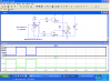
You can change the resistors as you suggest, but the result is that although the D1 and D2 'on' currents match, D2 doesn't fully turn off when D1 is on. See attached:
Why would D2 not be turning off fully? Because Q1 collector voltage is now higher? But Q1 is not shunting more or less current than before. Why did the value of R1 change (3k to 10k)?
I don't suppose it would make any difference if R3 was connected to the emitter versus being connected to the collector (connecting D3 between R2 and R3)?
Correct. So because R1 has been reduced Q1 collector voltage is higher. D3 still drops 0.6V, so D2 voltage is also higher and is enough to partly turn D2 on.
I was just playing about with the simulation. It makes little difference to the result.
I don't suppose it would make any difference if R3 was connected to the emitter versus being connected to the collector (connecting D3 between R2 and R3)?
The circuit you posted has R3 in the emitter (as I suggested). What would happen if R3 was attached to the collector; essentially connecting D3 to the center of a resistor divider. I suspect nothing. When Q1 was off there would be no flow through R3 to Q1 and when Q1 was on, the voltage drops would just be in a different order.
I like your solution. I'm just playing with it to see if/where it can be made robust; primarily in making sure D2 if off when it should be. Based on your comment "because R1 has been reduced Q1 collector voltage is higher. D3 still drops 0.6V, so D2 voltage is also higher and is enough to partly turn D2 on."; it may make sense to stack a second 1N4148 to raise the on voltage of D2 a little higher. This is where I was going with changing D3 to (low voltage) zener, something around slightly high than 1 volt. For me, I think seeing a zener in place of D3 shows (without thinking) that there is a cut over point for when D2 will light.
Thinking about the 2-pin dual LED and LM393, here's a circuit which should do the trick if both comparators in the LM393 chip are available. It would be preferable, though, to replace the LM393 with a comparator (or op-amp) IC having push-pull outputs, so that pull-up resistors could be eliminated to reduce component count.
Now I mean in this in the best possible way. That is a slick smart a$$ design. I saw the email text before I saw circuit in the forum and had the very distinct feeling of exactly what you did. I was right! The total extra cost over a single direct led is one resistor and the cost differential between the dual and single color LED.
Any one have any thoughts on how to run the bicolor LED from a standard open collector output? (and yes I realize the above designed two comparator circuit would work, but I am hoping for something without an extra IC)
This would do it (as has been proposed before). Note that R5 may need adjusting, depending on the 'low' output voltage of the comparator, to match the D1 and D2 currents.
This would do it (as has been proposed before). Note that R5 may need adjusting, depending on the 'low' output voltage of the comparator, to match the D1 and D2 currents.
Attached is a variation of a bi color single ended power supply circuit I posted in this thread when I saw the reference by ADW to this thread. It is a redraw of something I found a few years back on the web and used for an application. The transistors are 2N3904 but a 2N2222 or just about any common NPN switching transistor would work fine. The V+ is 12 volts but could be 5 volts. As drawn the LED current is about 21 mA, increasing R2 & R3 will reduce LED current. With A high one LED lights, with B high, the other, and with A & B high the astable MV runs and you get something like an Amber or Yellow (Red + Green) assuming a red / green LED. With A & B low, nothing going on.
Well watching it snow from a motel room in Clarksburg W. VA. and time to begin the trip home to Cleveland. Nice storm to drive in. I figure the normal 3.5 hour trip to take all day, should be fun! Could stay another day but want to get home. Damn snow.
Thinking about the 2-pin dual LED and LM393, here's a circuit which should do the trick if both comparators in the LM393 chip are available. It would be preferable, though, to replace the LM393 with a comparator (or op-amp) IC having push-pull outputs, so that pull-up resistors could be eliminated to reduce component count.
I used this circuit once as is and now I'm in need a variation. I've been try (unsuccessfully) to figure out how to drive a relay from just one of the comparator outputs or in parallel with one of the LEDs or pull-up resistors. I have found to catches:
1) The is the relay requires more current than the LED can handle. So I can't put the LED and relay in series.
2) The relay requires Vcc to ground power, so adding the additional voltage drop of the LED makes the relay turn on, shall we say, not so reliable.
How much current will the relay coil require? The comparator only has so much Output Sink Current to work with. Much any relay will likely require a driver transistor. The LED and current limiting resistor would parallel the relay coil along with a flyback diode. That would be my guess anyway.
The led can handle 20mA, the relay requires atleast 77mA. The obligatory diode is included.
I used this drawing as an equivalent circuit. The comparator is open collector but has poor Vsat characteristics. I can handle 20mA but only about 5mA with a decent Vsat. I plan to use a larger NPN for the circuit but in essence it would also be open collector where the loads would all be in the collector as well, and the emitter to ground. There's not much difference to whether I redraw the circuit with an external NPN open collector or just depict it the comparator.
The problem can't figure out is how to wire in the relay so it only comes on for one output and not with the other via the LED.
This site uses cookies to help personalise content, tailor your experience and to keep you logged in if you register.
By continuing to use this site, you are consenting to our use of cookies.

")
