Continue to Site

Welcome to our site!

Electro Tech is an online community (with over 170,000 members) who enjoy talking about and building electronic circuits, projects and gadgets. To participate you need to register. Registration is free. Click here to register now.

  • Welcome to our site! Electro Tech is an online community (with over 170,000 members) who enjoy talking about and building electronic circuits, projects and gadgets. To participate you need to register. Registration is free. Click here to register now.

LM3914 Temperature Sensor LM62 help please

k11m08

New Member
hi, i need some help with the circuit diagram. We have to make a PCB for the LM3914 with the temperaturesensor LM62. Now i need some help for the circuit diagram. Our Vcc(Vsource) is 5V and we want the whole temperaturerange of the Sensor 0-90°C. The LM 62 has an offset of 480mV at 0°C and rises with 15,6mV/°C. Can someone please send me a picture of the circuit diagram with all the values. We also have to connect a potentiometer to make some fine adjustments. I really need some help because I don't know how to connect those reference Pins with the resistors and how to calculate the resistors.
 
This might help :


Basically you have a range out of the LM62, so the 3914 must have that range setup
into it, dividers and offset.


Regards, Dana.
 
Last edited:
Have you read Danadak’s web page that was sent to you?

Hmmm…. I guess not.
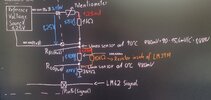
Yes i have read it. But i still don‘t know how i have to connect Pin 7 (REFout), Pin 8 (REFadj), Pin 6 (Rhi), Pin 5 (Sig) and Pin 4 (Rlo). My problem is that i don‘t know how to do it with the 480mV offset. Do i need 3 resistors know? And how do i calculate the resistors? I made a circuit diagram and connected Pin 7 —> R1 —> Pin 8, Pin 8–> Pin 6, Pin 6–>R2–> Pin 4, Pin 4–> R3–> Ground, Pin 5 —> Sensor Signal. Are the resistor values and corcuit diagram correct? I have also sent you a picture.
 

Attachments

  • IMG_6474.jpeg
    IMG_6474.jpeg
    1.2 MB · Views: 96

Latest threads

Back
Top