Continue to Site

Welcome to our site!

Electro Tech is an online community (with over 170,000 members) who enjoy talking about and building electronic circuits, projects and gadgets. To participate you need to register. Registration is free. Click here to register now.

  • Welcome to our site! Electro Tech is an online community (with over 170,000 members) who enjoy talking about and building electronic circuits, projects and gadgets. To participate you need to register. Registration is free. Click here to register now.

Logic Level Shifter or not?

Status
Not open for further replies.

Digl

New Member
Hi,
I am a total noob in this area so please forgive me if my question is total nonsene!
I want to substitute a button on a board with gpio from a nodemcu (3.3V) - the button is wired with 2 wires and uses 5V.
In a nut shell, I want to be able to control the "button pins" with the nodemcu.
I read that the nodemcu might be able to tolerate 5v on the pins - but that is probably not a nice solution.
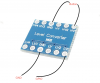
Can this be done with a Logic Level Shifter (I have a bidirectional LLC with LV,GND and LV1-4 on one side and the same for higher voltage (HV) on the other)?

Best Regards,
Digl
 
The official word from Espressif (makers of the ESP8266 used in the Node MCU) is that the digital pins are 5 volt tolerant, so you shouldn't have any problems at all.
 
Yes, that should work. Those level shifters are usually bi-directional, but you can run them in one direction only if you wish. I use one module to interface a GPS serial (3.3V) to an Arduino (5.0V). Serial really only runs one way, but like you say, why risk having 5V on a device that expects 3.3V, even if they are "5V tolerant"
 
Thanks for the quick answers, I guess I could just use it without the LLC.
I would just like to know how I would have to wire it, because I'm interested.
Is my wiring in the attachment false?
I only have two wires from the button...
Thank you very much!
 

Attachments

  • Untitled 2.png
    Untitled 2.png
    296.5 KB · Views: 103
You have to wire in the LV (3.3V) and the HV (5.0V) as well. It won't work without the voltages and grounds. Grounds can be connected together (usually they are)
 
Why can't the button use 3.3V? Button between pin and ground and a pullup resistor to 3.3V.

Mike.
 
Don't complicate your life. The esp pins can handle 5volts.
 
Hi!
Since I don't have have a power pin on the board with the button, I will not over complicate it and just use it directly.

I didn't want to use 3v on the button because it controls a relay and I wasn't sure if the relay would trigger with 3v...

Thank you all for your help!
Happy Easter
 
If you don't want to put 5v on the esp pin, you can use code to translate the button press to a transistor base to drive your relay.

AB02CFA5-135C-445E-8F95-DD5704FCC439.jpeg
 
Last edited:
Make sure there's a transient-suppression diode (e.g. 1N4148) across the relay coil (cathode to positive).
 
Make sure there's a transient-suppression diode (e.g. 1N4148) across the relay coil (cathode to positive).

fixed - thank you.
 
Status
Not open for further replies.

Latest threads

New Articles From Microcontroller Tips

Back
Top