Continue to Site

Welcome to our site!

Electro Tech is an online community (with over 170,000 members) who enjoy talking about and building electronic circuits, projects and gadgets. To participate you need to register. Registration is free. Click here to register now.

  • Welcome to our site! Electro Tech is an online community (with over 170,000 members) who enjoy talking about and building electronic circuits, projects and gadgets. To participate you need to register. Registration is free. Click here to register now.

Is it possible to make a gate level digital wrist watch

Fluffyboii

Active Member
Hi,
Ever since I designed and simulated a digital watch with logic gates for one of my electronics classes in university I had this urge to take that design and make it reality with only transistors. Not even logic gates or flip flops. I did find that it is already done my different individuals and it is not an easy feat.

Anyway I am super into digital watches for the past year or so. I simply like telling the precise time at a simple glance and I love the unusual shape and sizes some digital watches have. Today the idea of making my own digital wrist watch got stuck on my mind. Obviously the easiest way to do it would be to get a microprocessor, few small 8 bit displays, rtc module for precise time keeping, slamming all of that in a 3d printed case. Even doing that would be a feat in itself.
Unfortunately using something like an Arduino, taking the Atmega something processor from it feels wrong. People make smartwatches with lots of functionality with those and just simple time keeping with it would make me sad. I could get a less powerful microprocessor and try to code in assembly to torture myself but I am not in that mood.
Using transistor level logic would never fit in a wrist watch form factor, I wonder if using smd versions of logic gate chips, flip flops, multiplexers, etc. would make it possible to fit in a wrist watch or do I need to get counter ICs and other more complex ICs for it to fit. Today most wrist watches that are digital have a small mcu, a quartz crystal with an inductor, few caps and resistors and thats it. Pretty boring and unrepairable.

I am also curious about when something stops being analog. Analog circuits are fascinating. I also want to make a calculator with all solid state components but analog in design. Adding and subtracting with op amps is easy enough but multiplication is difficult :( Obviously having it all solid state requires using some kind if led display which requires a dac at some point. Can something similar be done with a watch, nearly fully analog except the display. This is bit off topic from my initial wrist watch idea but is it possible to make a watch with a led display that does all the time keeping with an analog circuitry, just for the sake of it. Something like a RC circuit that charges a capacitor until a voltage threshold is passed that the triggers a comparator for example to keep time. I never truly understood when some circuit truly becomes digital.

This is just my random thoughts at 5am.
Edit: I just searched bit more and a microprocessor less watch requires immense amount of logic elements just as I remember that will definitely not fit in a small package unless I use ICs to do most of the hard work.
 
Last edited:
For a cheap and low power self-setting add-on, use a time signal receiver; DCF77, WWVB or whatever suits the location.

You need a single input on the MCU (or an output as well to power the receiver if you don't want it on continuously).

eg.

 
Hi,
Ever since I designed and simulated a digital watch with logic gates for one of my electronics classes in university I had this urge to take that design and make it reality with only transistors. Not even logic gates or flip flops. I did find that it is already done my different individuals and it is not an easy feat.

Anyway I am super into digital watches for the past year or so. I simply like telling the precise time at a simple glance and I love the unusual shape and sizes some digital watches have. Today the idea of making my own digital wrist watch got stuck on my mind. Obviously the easiest way to do it would be to get a microprocessor, few small 8 bit displays, rtc module for precise time keeping, slamming all of that in a 3d printed case. Even doing that would be a feat in itself.
Unfortunately using something like an Arduino, taking the Atmega something processor from it feels wrong. People make smartwatches with lots of functionality with those and just simple time keeping with it would make me sad. I could get a less powerful microprocessor and try to code in assembly to torture myself but I am not in that mood.
Using transistor level logic would never fit in a wrist watch form factor, I wonder if using smd versions of logic gate chips, flip flops, multiplexers, etc. would make it possible to fit in a wrist watch or do I need to get counter ICs and other more complex ICs for it to fit. Today most wrist watches that are digital have a small mcu, a quartz crystal with an inductor, few caps and resistors and thats it. Pretty boring and unrepairable.

I am also curious about when something stops being analog. Analog circuits are fascinating. I also want to make a calculator with all solid state components but analog in design. Adding and subtracting with op amps is easy enough but multiplication is difficult :( Obviously having it all solid state requires using some kind if led display which requires a dac at some point. Can something similar be done with a watch, nearly fully analog except the display. This is bit off topic from my initial wrist watch idea but is it possible to make a watch with a led display that does all the time keeping with an analog circuitry, just for the sake of it. Something like a RC circuit that charges a capacitor until a voltage threshold is passed that the triggers a comparator for example to keep time. I never truly understood when some circuit truly becomes digital.

This is just my random thoughts at 5am.
Edit: I just searched bit more and a microprocessor less watch requires immense amount of logic elements just as I remember that will definitely not fit in a small package unless I use ICs to do most of the hard work.
Hi F,
Analog would be a much better piece of art, with a Barney Rubble type face, or like an old car speedometer. Wouldn't moving hands by coils or similar be more fun? It would have to be a clock though.
C
 
Hi Mr a,
If GPS modules are accepted for this project, they are very accurate.
C.

Oh for sure, but I think that adds an addition layer of complexity which I never wanted. That's of course unless I wanted the GPS function for the GPS function as well as timekeeping.

In the old days we used NIST WWV :)
 
Oh for sure, but I think that adds an addition layer of complexity which I never wanted. That's of course unless I wanted the GPS function for the GPS function as well as timekeeping.

In the old days we used NIST WWV :)
Hi Mr A,
If you want accuracy and simplicity, just use the 1/second trigger for your clock, with the minimum of satellites needed.
C
 
Hi Mr A,
If you want accuracy and simplicity, just use the 1/second trigger for your clock, with the minimum of satellites needed.
C

Hi,

Yes I'm sure you do, but I don't need that I just use one of the better RTC boards. They are already assembled and all, so you just connect a few wires to your Arduino and you have some really accurate time keeping. I can live with 6 seconds per year or something like that :)

Do you have a GPS module, and if so, where did you purchase it? Maybe I'll look into it anyway. Thanks.
Hi Mr A,
I have many GPS modules, up to M9Ns. I try to buy the latest, I can afford as I need a few for my project,
If you want to take a chance with these:

they will be ok for the 1/sec output, but are most likely clones, so you will need to buy the genuine modules from Ublox, and solder them onto boards like this, so you have all of the connections etc.

With these you will need at least one satellite, for the accurate clock.
An interesting thing is: if you switch yours on and I switch mine on, then they will be almost in sync. (within uS) I was going to make a project with TX and RX, to by synced with these.
Cheers, C.
 
With these you will need at least one satellite, for the accurate clock.

You need several satellites (three or more), to give a 3D fix, for the clock to be fully accurate - with only one or two, it cannot accurately measure its location & calculate the propagation delay from the satellites to the receiver.

With a good 3D lock, the PPS output from the better ublox modules is rated for an accuracy of around +/- 5nS

I have a Z9T running an RTK base station & NTP server, that's typically showing around 30 satellites with good signal strength.


You can get also boards with just a GPS receiver module that are a direct plug-in connection to such as a Raspberry Pi standard header.

The 60 or 77KHz receivers are far simpler and cheaper though, if you just want normal clock accuracy without having to bother with setting or checking them.
 
. I never truly understood when some circuit truly becomes digital.
If the signal has discrete values that represent a logic (boolean) state, it's digital.
If the signal has no discrete states, but continuous values, it's analog.
 
You need several satellites (three or more), to give a 3D fix, for the clock to be fully accurate - with only one or two, it cannot accurately measure its location & calculate the propagation delay from the satellites to the receiver.

With a good 3D lock, the PPS output from the better ublox modules is rated for an accuracy of around +/- 5nS

I have a Z9T running an RTK base station & NTP server, that's typically showing around 30 satellites with good signal strength.


You can get also boards with just a GPS receiver module that are a direct plug-in connection to such as a Raspberry Pi standard header.

The 60 or 77KHz receivers are far simpler and cheaper though, if you just want normal clock accuracy without having to bother with setting or checking them.
Hi R,
I was suggesting that by using a GPS module, there is a 1/sec output, for his watch/clock, this only needs one satellite, to fire.
C
 
This is what I made, I like it but it needs some work on the software.
IMG_2068.jpg
IMG_2088.jpg
 
I never truly understood when some circuit truly becomes digital.
All logic ICs have analog characteristics albeit non-linear since there is no gain when the output is limited but there is gain at the transition threshold. It is considered logic when it obeys the voltage level rules and has any fundamental logic functions: INV, OR, NOR, XOR, XNOR, AND, NAND. Different logic levels are rules defined for each topology and supply levels for ECL, TTL, CML, NMOS, and CMOS.

Some analog circuits, such as analog comparators with pullup R, may interface with logic.
Diode bridges act as XOR gates with the appropriate input voltages.
Also, the 4000 series CMOS with low current shoot-thru could easily be analog inverting amplifiers with negative feedback, since they had 60 dB gain.
 
I just saw this metal 3D printed watch case on reddit and it made me want to make a wrist watch once again. I gave the borrowed pickit 2 back to my professor though.

I am debating of buying a pickit3 or pickit2 at the moment. If I get pickit3 I can program PICs that have more pins to drive more segments, generally it makes more sense even if I decide to use the same PICs since the price difference between the two is not a lot. I found a original looking pickit2 in my area though, if it is really original I may grab it.

I wonder if I should go with a rechargeable battery or a simple watch. I do not want to create a smart watch so first option does not seem very appealing to me. But the battery life will be bad if I use a coin cell because my PICs have internal linear voltage regulators. But I can swap them out at with the no LTO version without changing the code or pcb I guess.
 
I just saw this metal 3D printed watch case on reddit and it made me want to make a wrist watch once again. I gave the borrowed pickit 2 back to my professor though.

I am debating of buying a pickit3 or pickit2 at the moment. If I get pickit3 I can program PICs that have more pins to drive more segments, generally it makes more sense even if I decide to use the same PICs since the price difference between the two is not a lot. I found a original looking pickit2 in my area though, if it is really original I may grab it.

You're far better off with a 3 than a 2, but even better would be a 4 or the new 5 (I'm considering ordering a 5) - the 2 only supports fairly old PIC's, and the 3 doesn't support many newer ones - and both 2 and 3 are no longer supported in the newest versions of MPLABX.

I wonder if I should go with a rechargeable battery or a simple watch. I do not want to create a smart watch so first option does not seem very appealing to me. But the battery life will be bad if I use a coin cell because my PICs have internal linear voltage regulators. But I can swap them out at with the no LTO version without changing the code or pcb I guess.

PIC's don't have internal voltage regulators, presumably you mean your PCB's include external ones?. For a 3.3V regulator I use the MicroChip MCP1700-3302 (they do a 5V version as well), these are low drop out, and VERY low quiescent current. One thing to bear in mind though, the pin connections are different to the LM78L0X series.

Using a PIC based clock/watch the power concerns are the display, the PIC (left mostly in sleep) uses almost nothing, and so does the MCP1700-3302.
 
You're far better off with a 3 than a 2, but even better would be a 4 or the new 5 (I'm considering ordering a 5) - the 2 only supports fairly old PIC's, and the 3 doesn't support many newer ones - and both 2 and 3 are no longer supported in the newest versions of MPLABX.


PIC's don't have internal voltage regulators, presumably you mean your PCB's include external ones?. For a 3.3V regulator I use the MicroChip MCP1700-3302 (they do a 5V version as well), these are low drop out, and VERY low quiescent current. One thing to bear in mind though, the pin connections are different to the LM78L0X series.

Using a PIC based clock/watch the power concerns are the display, the PIC (left mostly in sleep) uses almost nothing, and so does the MCP1700-3302.
I do not know the exact power usage of the PIC with LDO, but it consumes at least a magnitude order more power compared to the version that does not have a LDO built in.

In the super low power clock video I posted here some time ago, the guy powers his PIC (that does not have LDO) with 1.8V for highest power efficiency.

Anything other than PIC2 and PIC3 is not cloned and much more expensive. I am not sure if I will ever touch a PIC again after making what I want. There is a guy selling this original Pickit2 for about 20 dollars. I think I can sell it when I want something better for more on Ebay after I am done with it. I know it is identical with a clone in terms of functionality but it is nice to have the real thing anyway.
1723133615749.png

1723133360047.png
1723133473625.png
 
Hi,

I recently installed MPLAB on my desktop PC and noticed that the MCC (MPLAB Code Configurator) was installed by default. I'm curious about how I can use MCC to make programming the PIC more efficient and organized. I believe MCC should have an LCD menu where you can set up a basic LCD template and graphically assign pins to the LCD segments. However, I can't seem to find this feature. I came across a six-year-old video on YouTube (link:
), but it has no description or comments, and I can't locate the menu the author is using because the MPLAB UI has changed over time.

Manually assigning numbers and characters to these LCDs is quite time-consuming. If I need to change the pin layout for the LCD displays, I have to rewrite the entire code. For instance, if I want to use weak pull-ups, but they are only available on port B, and I've already coded port B pins for one of the LCDs, I would need to rewrite all the LCD-related code.

Regarding the PIC's power consumption, I recall that my LCDs require at least 3.3V to the VDD of the PIC to display properly. Using a lower voltage, like 1.8V for VDD, to minimize power usage isn't feasible, even with the PICFL1939. I don't think it's worth minimizing the microcontroller's power usage since it involves many compromises, such as avoiding the use of the LCD bias resistor ladder (which I can't avoid because my LCDs are multiplexed, and there aren't enough pins for static ones anyway as discussed before).

I really don't want to use a lithium battery for a simple wristwatch, even though I have some small lithium batteries on hand. However, if I use a coin cell and need to replace it every year, that won't be ideal either. I'm considering using the internal voltage reference and comparator of the PICF1939 to create a basic boost converter to increase the voltage from a supercapacitor as the power source. To charge the supercapacitor, I plan to either salvage small solar panels from old calculators or use a magnet moving inside a coil to generate AC current, which I can convert to DC with a full-bridge rectifier. From what I understand the comparator of the PIC can initiate an interrup if voltage drops under a set threshold. But I am not exactly sure if it is possible to both regulate power and keep time with one PIC.

My question is: Is it possible to use a hollow toroid coil with a spherical magnet rolling inside to generate a meaningful amount of power when the watch moves with the wearer's hand? I think it would look cool if the watch had a coil around it generating power through movement. If that's not feasible, maybe a magnet moving along single axis, like in those shake-to-charge flashlights, could work. I would not mind cranking a lever or just "winding" some small DC motor with high gear ratio to charge the watch, but I do not want to make something too mechanically complex as it would be hard to 3D print.

1723854349445.png

1723854364591.png

Essencially I want the electrical equievelent of the automatic watch mechanism that winds a spring.
1723854755900.jpeg

I still do not know where to start with the programming. I do not want to go to extreme with bare metal C programming a PIC because I felt the comfort of using an Arduino but it seems like that is unavoidable.
 
My question is: Is it possible to use a hollow toroid coil with a spherical magnet rolling inside to generate a meaningful amount of power when the watch moves with the wearer's hand? I think it would look cool if the watch had a coil around it generating power through movement. If that's not feasible, maybe a magnet moving along single axis, like in those shake-to-charge flashlights, could work. I would not mind cranking a lever or just "winding" some small DC motor with high gear ratio to charge the watch, but I do not want to make something too mechanically complex as it would be hard to 3D print.

Some Seiko watches use a movement-driven generator:

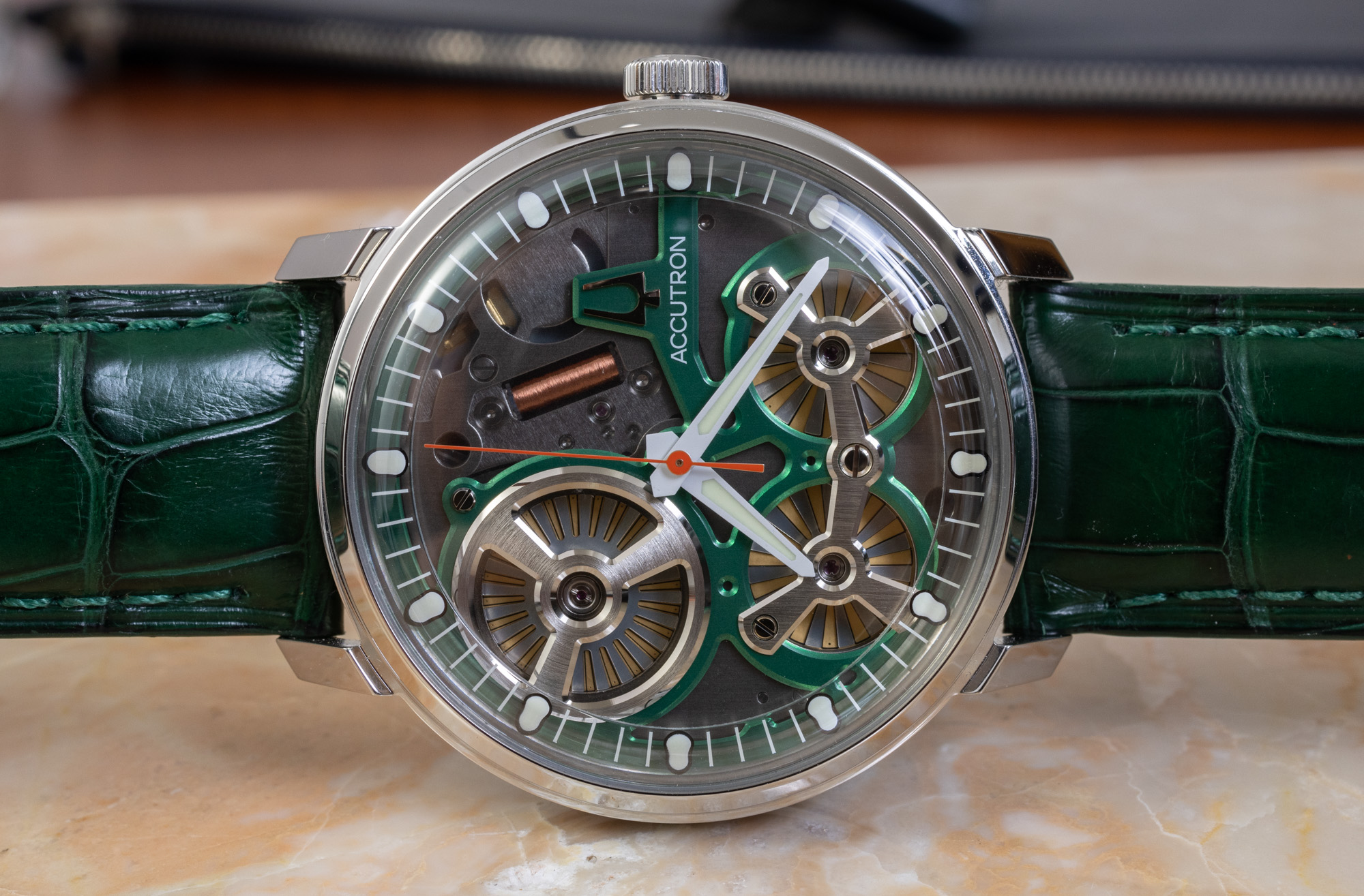
A recent Bulova watch movement claims to use an electrostatic generator & motors, looking rather like tiny Wimshurst machines:
 
Some Seiko watches use a movement-driven generator:

A recent Bulova watch movement claims to use an electrostatic generator & motors, looking rather like tiny Wimshurst machines:
Damn that Bulova watch is quite beautiful only if it did not cost 3650 dollars.
 

New Articles From Microcontroller Tips

Back
Top