Hi all,
can someone familiar with LTSpice please figure this out? I'm trying to work out a simple "soft start" circuit for a simple transformer-rectifier-smoothing cap power source, that will be connected to a 60V high current transformer, to avoid any possibility of damaging a 1A bridge if it's turned on near a voltage peak.
For the sim I'm just using a fixed 90V DC input, on the basis that's going to be a higher surge that on rectified AC.
The problem is, the bypass FET is conducting at the instant the sim starts?? I've tried setting the initial condition on the caps, but to no effect. Any ideas appreciated! The component values are not final, just approximations until I work out the dissipation.
ps. I did figure out once how to plot power dissipation in a component - but now I cannot remember; it is two years since I last ran the simulator, from what it said about updates!
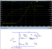
Circuit & plot - note the initial spike on the blue trace, which is current through P channel FET U1.
The green trace is the voltage on the main smoothing cap.

Simulator file attached.
The FET model is from the an Infineon model pack on github, here:

 github.com
can someone familiar with LTSpice please figure this out? I'm trying to work out a simple "soft start" circuit for a simple transformer-rectifier-smoothing cap power source, that will be connected to a 60V high current transformer, to avoid any possibility of damaging a 1A bridge if it's turned on near a voltage peak.
For the sim I'm just using a fixed 90V DC input, on the basis that's going to be a higher surge that on rectified AC.
The problem is, the bypass FET is conducting at the instant the sim starts?? I've tried setting the initial condition on the caps, but to no effect. Any ideas appreciated! The component values are not final, just approximations until I work out the dissipation.
ps. I did figure out once how to plot power dissipation in a component - but now I cannot remember; it is two years since I last ran the simulator, from what it said about updates!
Circuit & plot - note the initial spike on the blue trace, which is current through P channel FET U1.
The green trace is the voltage on the main smoothing cap.
Simulator file attached.
The FET model is from the an Infineon model pack on github, here:
GitHub - metacollin/LTspiceInfineonNMOSLibrary: Over 7000 Infineon NMOS and PMOS Power MOSFET models - for LTspice!
Over 7000 Infineon NMOS and PMOS Power MOSFET models - for LTspice! - metacollin/LTspiceInfineonNMOSLibrary


