Continue to Site

Welcome to our site!

Electro Tech is an online community (with over 170,000 members) who enjoy talking about and building electronic circuits, projects and gadgets. To participate you need to register. Registration is free. Click here to register now.

  • Welcome to our site! Electro Tech is an online community (with over 170,000 members) who enjoy talking about and building electronic circuits, projects and gadgets. To participate you need to register. Registration is free. Click here to register now.

LTSpice initial conditions help, please?

rjenkinsgb

Well-Known Member
Most Helpful Member
Hi all,
can someone familiar with LTSpice please figure this out? I'm trying to work out a simple "soft start" circuit for a simple transformer-rectifier-smoothing cap power source, that will be connected to a 60V high current transformer, to avoid any possibility of damaging a 1A bridge if it's turned on near a voltage peak.

For the sim I'm just using a fixed 90V DC input, on the basis that's going to be a higher surge that on rectified AC.

The problem is, the bypass FET is conducting at the instant the sim starts?? I've tried setting the initial condition on the caps, but to no effect. Any ideas appreciated! The component values are not final, just approximations until I work out the dissipation.

ps. I did figure out once how to plot power dissipation in a component - but now I cannot remember; it is two years since I last ran the simulator, from what it said about updates!

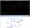
Circuit & plot - note the initial spike on the blue trace, which is current through P channel FET U1.
The green trace is the voltage on the main smoothing cap.

RJ_Softstart.jpg


Simulator file attached.
The FET model is from the an Infineon model pack on github, here:
 

Attachments

  • Switch-on_sim.asc
    1.6 KB · Views: 37
I think I know what your asking.
What you do is in the parameters for the cap, in the field for the voltage you type "ic=v".
v is your initial voltage.
 
ctrl<mouse click> with the cursor over the trace title gets you the power.
ctrl alt with the cursor over the component gets you the power.
 
The problem is, the bypass FET is conducting at the instant the sim starts?
When I run the sim (albeit using a different PFET) the FET switches on at about 80-90mS.
1732218356343.png
 
When I run the sim (albeit using a different PFET) the FET switches on at about 80-90mS.

When I run it, the wanted conduction starts at somewhere around 150mS; presumably different gate thresholds.

The problem on mine is that there is a high current pulse through the FET in the first couple of milliseconds, causing the capacitor voltage to rise abnormally - then it turns off until the gate cap actually charges to a suitable voltage.

Your run shows a smooth charge curve without that initial kick.

What FET are you using & what version of LTSpice? I wonder if the FET model is bad, or incompatible?
 
What you do is in the parameters for the cap, in the field for the voltage you type "ic=v".
v is your initial voltage.
That's what I though it should be? I have ic=0 to start the cap at zero volts, but the FET is still turned on in the first couple of milliseconds. As it works OK for Alec when using a different FET, it looks like a bad or incompatible model.

Also thanks for the tip about the power.
 
My sim:
I think you may have a faulty MOSFET model.

1732234095723.png
 
I think you may have a faulty MOSFET model.

Indeed.. I go that impression from it working when Alec tried it.

I found that FET library package explicitly to try and get a model with real-world parameters of a device I can buy, so I could set the timing without too many mods to an actual circuit.

Oh well.. That's why I so rarely touch a simulator & prefer using real components!
 
I found that FET library package explicitly to try and get a model with real-world parameters of a device I can buy
Where did you find that model?
 
You might try simulating the MOSFET by itself to see its characteristics, such as the threshold voltage, and see if it matches the data sheet.
 
The FET is just a bypass switch; what I'm really trying to calculate is the peak and total power dissipated in the charging resistor at switch on, and the peak current in that, to decide on suitable values and power ratings for different smoothing caps and voltages.

The faulty FET model was upsetting the initial charge, due to it momentarily passing current at near zero time.
 
I see two things....
The Zener is practically floating.
The divider is putting ~60 volts on the gate. The max gate voltage is +/-20V.:oops:
So I think the mosfet has been killed..;).

EDIT:
Download the library from Infineon.
Use the model value IPD40DP06NM_L0 when using a standard 3 terminal mosfet symbol.
 
Last edited:
The Zener is practically floating.
The divider is putting ~60 volts on the gate. The max gate voltage is +/-20V.:oops:
???
It's a P channel FET, with the 15V zener directly between gate and source.

The wanted action of the FET is fine, it was the zero time start-up glitch from the bad model that was messing the overall simulation up.

The target was to calculate the peak and total energy in the series power resistor; the FET is just a cut-off once the inrush has dropped to a low enough level.
 

New Articles From Microcontroller Tips

Back
Top