Continue to Site

Welcome to our site!

Electro Tech is an online community (with over 170,000 members) who enjoy talking about and building electronic circuits, projects and gadgets. To participate you need to register. Registration is free. Click here to register now.

  • Welcome to our site! Electro Tech is an online community (with over 170,000 members) who enjoy talking about and building electronic circuits, projects and gadgets. To participate you need to register. Registration is free. Click here to register now.

Maximums detector

Status
Not open for further replies.

efra_mt

New Member
Hi everyone!!

Can somebody help me with this issue?

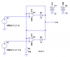
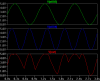
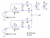
I need a system with 2 analog input signals (between 0-5V) and 1 analog output signal (same range) where the output signal is the maximum of both input signals. I mean, i want to compare the input signals and send the one that is bigger to the output. I can't do it just with a comparator because it will only conmute between Vdd or Vee when detecting one bigger than the other rigth? Is there some way to do this?? Thanks in advance

Best regards.

Efraín Martínez
 
One way would be to have both signals go to a differential comparator chip. The output of the comparator would then gate an analog switch to the larger signal. An LM339 is a common comparator IC but it's input does not go to the supply voltage, so you would have to operate it from a higher supply voltage for 5V inputs. RR (Rail-to-Rail) devices such as the LMC7215 will work to 5V with a 5V supply. A common analog switch is the CD4066.
 
Dough, I hoped you would've posted in the other thread because I suggested an analogue switch but you've given more detail so your post is better.

Yes, what's the supply voltage?

To use the LM393, you need a higher voltage than 5V because its inputs don't work all the way up to the supply voltage.

What happens when the two signals are within less than 0.1mV of each other? There's a risk of oscillation because the comparator might be biased in the linear region causing the analogue switches to chatter.
 
If the frequencies involved are low, you can use two precision rectifiers, analog OR'ed. See attached.
If the frequencies are high (I would guess above a few kHz), then op amp recovery time, slew rate, and bandwidth can cause switching glitches.
The comparator/analog switch scheme will have some of the same problems.
 

Attachments

  • maximums sch..PNG
    maximums sch..PNG
    11.8 KB · Views: 160
  • maximums waves..PNG
    maximums waves..PNG
    13.3 KB · Views: 149
  • maximums..asc
    1.8 KB · Views: 121
That's a good idea.

How sensitive do you think it is to differences between the op-amps?

I suppose if the op-amps are both on one IC they'll be near enough exactly the same.
 
That's a good idea.

How sensitive do you think it is to differences between the op-amps?

I suppose if the op-amps are both on one IC they'll be near enough exactly the same.
Even on separate chips, the only critical factor is input offset voltage, and unless the OP needs accuracy better than a few millivolts of error, it won't be an issue.
 
If the frequencies involved are low, you can use two precision rectifiers, analog OR'ed. See attached.
If the frequencies are high (I would guess above a few kHz), then op amp recovery time, slew rate, and bandwidth can cause switching glitches.
The comparator/analog switch scheme will have some of the same problems.
Using precision rectifiers would seem to be a better approach than using a comparator and switch.

To help with recover time, you could add another diode from each output (cathode) to its respective minus input (anode) to keep the op amp in its active region and prevent negative saturation of the amp with the lower input voltage. Of course, you also would need to add a resistor (say 10k) in series with the each minus input to avoid interaction between the two op amps.
 
Last edited:
Using precision rectifiers would seem to be a better approach than using a comparator and switch.

To help with recover time, you could add another diode from each output (cathode) to its respective minus input (anode) to keep the op amp in its active region and prevent negative saturation of the amp with the lower input voltage. If course, you also would need to add a resistor (say 10k) in series with the each minus input to avoid interaction between the two op amps.
Like this. I've done this before. Don't know why I didn't this time.
 

Attachments

  • maximums1 sch..PNG
    maximums1 sch..PNG
    13.7 KB · Views: 152
Hi everyone!!

Thank you for your answers and your time. I simulated the circuits and its pretty much what i was looking for. I was looking for another alternative for using the simple comparator and the analog switch because of the glitching you mencioned. I'm going to test the circuit and see how it works.

Thanks again!
 
Status
Not open for further replies.

Latest threads

New Articles From Microcontroller Tips

Back
Top