Hi,
Rather than post to an old thread, I thought I'd start a new one here.
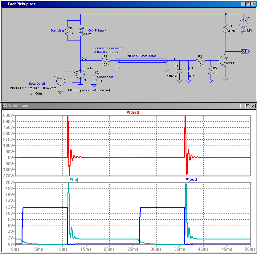
I was reviewing MikeML's engine tach circuit (which is great), but was just curious about the power dissipation needed in the resistors:
The original thread is here: thread
@MikeML,
Thanks for posting your tach signal condition circuit and simulation!
Just one question for you. In your design, wouldn't R3 have to be able to dissipate quite-a-bit of power? Using your simulation as a guide, if you had 630V as an input, would you not have (630V-0.65V)/(100k+10k)ohms=5.72mA going across R3? With a voltage drop of 100kohm*5.72mA = 572V for a total power dissipation of 572V*5.72mA = 3.27W? Granted, it would be a short duration and I presume the RC filter would help attenuate the spike, but just want to make sure I understand your circuit correctly...
Thanks!!!
Justin
Rather than post to an old thread, I thought I'd start a new one here.
I was reviewing MikeML's engine tach circuit (which is great), but was just curious about the power dissipation needed in the resistors:
The original thread is here: thread
@MikeML,
Thanks for posting your tach signal condition circuit and simulation!
Just one question for you. In your design, wouldn't R3 have to be able to dissipate quite-a-bit of power? Using your simulation as a guide, if you had 630V as an input, would you not have (630V-0.65V)/(100k+10k)ohms=5.72mA going across R3? With a voltage drop of 100kohm*5.72mA = 572V for a total power dissipation of 572V*5.72mA = 3.27W? Granted, it would be a short duration and I presume the RC filter would help attenuate the spike, but just want to make sure I understand your circuit correctly...
Thanks!!!
Justin
")
