mstechca
New Member
I am getting somewhat confused.
A number of you have seen my story on my superregen receiver posted here in different threads over the past few months, and a number of you have made good suggestions.
So after I realized that my design had distortion at loud volume, I thought I should take a different approach similar to what a number of you recommend.
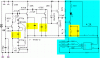
In every amplifier stage, except for the power amplifier stage, I have added a 4.7K resistor and a capacitor in series to form the "miller" circuit.
It seems that the sound quality is much better, but the volume is a little bit reduced.
I have chosen resistor values based on the voltages at the base of each NPN transistor.
I think that the emitter current and collector current must be the same for optimal transistor operation.
I am going to try to choose different value resistors to obtain more gain.
Right now, my detector has an 18K pull-up resistor, an 82K 1% resistor from base to the 18K pull-up resistor, and a 4.7K resistor between emitter and the tank circuit that is connected to ground.
The circuit won't work if the voltage is under 6. It will work at 3V if the pull-up is changed to about 10K.
I plan to decrease the pull-up resistor, but I want to know my limits before creating component "bombs" (you know, circuits that blow up when they start). Also, I want to make the amplitude larger, and I'm afraid if the 82K resistor goes too low, then I think the gain will go too low.
The transistor I am dealing with is a Pn3563.
I'll see what I can personally come up with
I intend to add 10 or more uF bypass capacitors to the 4.7K resistors.
A number of you have seen my story on my superregen receiver posted here in different threads over the past few months, and a number of you have made good suggestions.
So after I realized that my design had distortion at loud volume, I thought I should take a different approach similar to what a number of you recommend.
In every amplifier stage, except for the power amplifier stage, I have added a 4.7K resistor and a capacitor in series to form the "miller" circuit.
It seems that the sound quality is much better, but the volume is a little bit reduced.
I have chosen resistor values based on the voltages at the base of each NPN transistor.
I think that the emitter current and collector current must be the same for optimal transistor operation.
I am going to try to choose different value resistors to obtain more gain.
Right now, my detector has an 18K pull-up resistor, an 82K 1% resistor from base to the 18K pull-up resistor, and a 4.7K resistor between emitter and the tank circuit that is connected to ground.
The circuit won't work if the voltage is under 6. It will work at 3V if the pull-up is changed to about 10K.
I plan to decrease the pull-up resistor, but I want to know my limits before creating component "bombs" (you know, circuits that blow up when they start). Also, I want to make the amplitude larger, and I'm afraid if the 82K resistor goes too low, then I think the gain will go too low.
The transistor I am dealing with is a Pn3563.
I'll see what I can personally come up with
I intend to add 10 or more uF bypass capacitors to the 4.7K resistors.