Menticol
Active Member
Hello everyone!
Some months ago I made two (very simple) audio related projects, but both of them failed: The first one isn't serious, but the second was catastrophic. I have a couple of questions since then, and I hope you can (laugh) and help me.
Case 1:
I got a very nice stereo "UV meter" (scrapped from a 1970's receiver) and wired it to my home theater. Actually is not a VU meter, it's labeled POWER W and it has an odd scale (0.3-1-3-5-10-20-30-60), but I don't mind, is just for aesthetic purposes.
The indicator is connected in parallel to the home theater speaker lines (I used a small diode and a resistor in series to make it work). The problem is, every time I crank the volume too high, the needle jumps out of the scale. As expected.
Question: Using a larger resistor (to keep the needle on scale) will damage the amplifier? What's the correct way to limit the needle movement without messing the impedance?
________________________
Case 2:
My DIY project required to add a "Line In" to a cheap 1980's sony boombox, to be used with an external mp3 player. Tried to use the cassette head line - didn't worked, sound was awful. I attribute it to impedance mismatch.
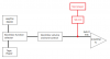
Then I tested another approach, one that I successfully used before on another boombox: Connecting the external mp3 player directly to the amplifier input pins. It worked great, but volume and tone controls were unusable (I totally bypassed them, so that was expected). To fix the problem I made a simple volume control (see the attached file) and connected it between the player and the IC.
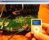
It worked, and guess what: Boombox's original volume control magically started to work too. I happily glued my potentiometer on a hidden place, and assembled the unit. Proceeded to use my new creation... and the mp3 player burned after 5 minutes
Question: Where is the fault, on the volume control or the gross amplifier connection? I didn't detected any voltage coming out of my Line In, and the same approach works great on other equipment
Thank you very much for any input guys. By the way the song's title on the picture says it all, it's a shame.
Some months ago I made two (very simple) audio related projects, but both of them failed: The first one isn't serious, but the second was catastrophic. I have a couple of questions since then, and I hope you can (laugh) and help me.
Case 1:
I got a very nice stereo "UV meter" (scrapped from a 1970's receiver) and wired it to my home theater. Actually is not a VU meter, it's labeled POWER W and it has an odd scale (0.3-1-3-5-10-20-30-60), but I don't mind, is just for aesthetic purposes.
The indicator is connected in parallel to the home theater speaker lines (I used a small diode and a resistor in series to make it work). The problem is, every time I crank the volume too high, the needle jumps out of the scale. As expected.
Question: Using a larger resistor (to keep the needle on scale) will damage the amplifier? What's the correct way to limit the needle movement without messing the impedance?
________________________
Case 2:
My DIY project required to add a "Line In" to a cheap 1980's sony boombox, to be used with an external mp3 player. Tried to use the cassette head line - didn't worked, sound was awful. I attribute it to impedance mismatch.
Then I tested another approach, one that I successfully used before on another boombox: Connecting the external mp3 player directly to the amplifier input pins. It worked great, but volume and tone controls were unusable (I totally bypassed them, so that was expected). To fix the problem I made a simple volume control (see the attached file) and connected it between the player and the IC.
It worked, and guess what: Boombox's original volume control magically started to work too. I happily glued my potentiometer on a hidden place, and assembled the unit. Proceeded to use my new creation... and the mp3 player burned after 5 minutes
Question: Where is the fault, on the volume control or the gross amplifier connection? I didn't detected any voltage coming out of my Line In, and the same approach works great on other equipment
Thank you very much for any input guys. By the way the song's title on the picture says it all, it's a shame.
Attachments
Last edited: