Continue to Site

Welcome to our site!

Electro Tech is an online community (with over 170,000 members) who enjoy talking about and building electronic circuits, projects and gadgets. To participate you need to register. Registration is free. Click here to register now.

  • Welcome to our site! Electro Tech is an online community (with over 170,000 members) who enjoy talking about and building electronic circuits, projects and gadgets. To participate you need to register. Registration is free. Click here to register now.

Need a diagram for 24v Battery Monitor using LM3914 chip

Status
Not open for further replies.

sprat

New Member
Hi
I have 2-12v batteries connected in series (24v). Can someone help me with a circuit diagram using lm3914 chip to monitor the voltage state. I have looked around but all I can find is a 12v diagram. I would like to lowest to be 21v and the highest to be 29v
Any help will be greatly appreciated
 
Do you want to power the entire monitoring circuit off the battery you are monitoring? Dot mode or bar mode?
 
sprat said:
Yes I would like to power it from the batteries. I would prefer bar mode

Thanks
I'll try to design it for you. Bear in mind that bar mode will draw more current than dot mode. It's easy to change, though. You can install a switch if you wish.
 
I haven't tested this, but I don't think I screwed anything up. :roll:
 

Attachments

  • lm3914_expanded_voltmeter3.png
    lm3914_expanded_voltmeter3.png
    38.6 KB · Views: 4,430
Sprat, what is attached your battery? I just realized that, if the load (or an alternator/generator) generates noise spikes on the battery, we may need to add filtering in front of the LM317.
 
sprat said:
The batteries are running my UPS.
I edited the schematic, adding 10ms of filtering in front of the LM317. I hope that's enough. The max power dissipation of the LM317 will be more like 1.5 watts with the change, instead of 2 as indicated on the schematic.
 
Hi Ron,

I suggest an alternative, for discussion purposes only.

I have not used the L3914 before so this might not work.

The power supply LM317 is similar to yours and outputting 15V. I would then setup the LM3914 to gives a 10V reference voltage, with RLO grounded. So the scale for SIG input becomes 0-10V for 10 LEDs.

I'll then use a TL431 to drop a constant 20V from the input signal before feeding this to the LM3914 SIG input.

The first LED will light at 21V and the last at 30V, giving a one volt step per LED.

Do you think this will work?
 
Something like that should work, although I don't see how you can use a TL431 to level shift down to 1.0V. I gave some thought to a level shifter that would do that, but concluded the attenuator would be simpler.
 
Ron H said:
Something like that should work, although I don't see how you can use a TL431 to level shift down to 1.0V. I gave some thought to a level shifter that would do that, but concluded the attenuator would be simpler.

The TL431 is a shunt regulator or adjustable voltage zener which need just 0.5mA or higher to maintain regulation. Using external resistors, the terminal voltage can be trimmed to any value from 2.5V to over 30V.

My suggestion works like this. If the battery voltage is 24V, the voltage across the TL431 is always 20V(Constant), then the voltage scross the bottom resistor must be at 4V.
 

Attachments

  • tl431.gif
    tl431.gif
    3.4 KB · Views: 2,136
Hiya Ron,
Eh mate thanks very much for designing that battery circuit :D 
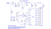
I've been looking on the web for ages trying to find a circuit so I can monitor my 24 volt battery bank in my shed. One query as I'm inputting pure DC from a solar array I should be able to simplify the input side thru the lm317 as spikes won't be a problem. Oh if if I may dare I've got a bank of Nife batteries which float around 16.5 volts so how would I modify the circuit to suit. Silly me used my 12 volt lm3914 circuit and ended up seeing the magic smoke :cry:

Cheers Bryan :D
 
Status
Not open for further replies.

Latest threads

New Articles From Microcontroller Tips

Back
Top