Roff
Well-Known Member
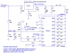
You can probably eliminate R11 and C5.bryan1 said:Hiya Ron,
Eh mate thanks very much for designing that battery circuitI've been looking on the web for ages trying to find a circuit so I can monitor my 24 volt battery bank in my shed. One query as I'm inputting pure DC from a solar array I should be able to simplify the input side thru the lm317 as spikes won't be a problem. Oh if if I may dare I've got a bank of Nife batteries which float around 16.5 volts so how would I modify the circuit to suit. Silly me used my 12 volt lm3914 circuit and ended up seeing the magic smoke :cry:
Cheers Bryan
What range do you want for the NiFe battery?