Continue to Site

Welcome to our site!

Electro Tech is an online community (with over 170,000 members) who enjoy talking about and building electronic circuits, projects and gadgets. To participate you need to register. Registration is free. Click here to register now.

  • Welcome to our site! Electro Tech is an online community (with over 170,000 members) who enjoy talking about and building electronic circuits, projects and gadgets. To participate you need to register. Registration is free. Click here to register now.

Need help designing 7 segment display.

Status
Not open for further replies.
So I recently got my hands on a box of ne-2 neon bulbs and I wanted to make a 7 segment display with those bulbs but I need an opinion on how to interface an Arduino to them. I was thinking I could run the bulbs in parallel, (like in the picture below) and have a relay on each bulb. (Yes, I know I drew switches not relays on the schematic). It would probably be 2 bulbs per segment actually, but for simplicity sake I drew the schematic with 1. Is there a better way to do this than just connecting an Arduino to the relays?

Also I know I can just buy a 7 segment display, but where's the fun in that.

Thanks in advance -Ray
 

Attachments

  • 15962505813592777473186515745303.jpg
    15962505813592777473186515745303.jpg
    1.1 MB · Views: 322
I don't think that's going to work. The drive to neon bulbs needs to be current limited. A high voltage is needed to light the bulb, but then the current limiting drops the voltage. With bulbs in parallel, the bulb with the lowest strike voltage will start conducting, dropping the voltage so no other bulbs will illuminate.
 
You need a DC supply somewhere around 150V or so, plus a current limiting resistor for each separate neon to set the brightness.
Connect each neon and resistor combination to the +150V.

Then switch the other end of the neon+resistor combination (or two or more parallel combinations) to ground using a transistor rated over 100V.

If you look at "Nixie tube clock schematics" you can pretty much use all the same driver circuits they do, as nixies are in essence neon lamps with multiple shaped electrodes in a shared glass envelope.
 
Last edited:
So I recently got my hands on a box of ne-2 neon bulbs and I wanted to make a 7 segment display with those bulbs but I need an opinion on how to interface an Arduino to them. I was thinking I could run the bulbs in parallel, (like in the picture below) and have a relay on each bulb. (Yes, I know I drew switches not relays on the schematic). It would probably be 2 bulbs per segment actually, but for simplicity sake I drew the schematic with 1. Is there a better way to do this than just connecting an Arduino to the relays?

Also I know I can just buy a 7 segment display, but where's the fun in that.

Thanks in advance -Ray

As already mentioned, each neon needs it's own current limiting resistor - they are rather like LED's in that way.

For that matter, why not just use LED's? - better light, longer life, no high voltages required - it seems pointless using poorer old technology that will cost a LOT more to build, simply for the sake of using something old you have.

But assuming you want to?, if using two neons per segment, then you can put those two in series with a single limiting resistor - BUT you need an even higher voltage to supply them. Neons usually need between 60V and 90V, so it soon adds up if putting them in series.
 
the good news:
Your idea is fine, except you'll need a 220k resistor in series with EACH neon and one relay for each segment as in the photo below. The Neon will need a strike voltage of 90v and then drop down to 60v while running. This sounds complicated to control but a simple 220k resistor does the job with a 120vAC supply - you simply need one resistor in series per NE-2 to prevent the first to strike from preventing the rest from striking.

the bad news:
You'll need AC power source for the best performance of an Neon (DC will only illuminate one of the two electrodes).
DC in each polarity on the left, snd AC is the right-most

A relay circuit is below (with Arduino).
Also, you can use the neons for other things - even relaxation oscillators that use the "negative resistance" of the neon.
here are some ideas...

C4E004EA-01AE-4F41-867E-08ACC1627822.jpeg


C79F3305-B221-4D93-9192-DB8398EEC0EC.jpeg
 
As already mentioned, each neon needs it's own current limiting resistor - they are rather like LED's in that way.

For that matter, why not just use LED's? - better light, longer life, no high voltages required - it seems pointless using poorer old technology that will cost a LOT more to build, simply for the sake of using something old you have.

But assuming you want to?, if using two neons per segment, then you can put those two in series with a single limiting resistor - BUT you need an even higher voltage to supply them. Neons usually need between 60V and 90V, so it soon adds up if putting them in series.
Do you think a setup like this would work? I also know about the current limiting resistors I just didn't draw them in the schematic.
 

Attachments

  • 15963150786308076173083892695686.jpg
    15963150786308076173083892695686.jpg
    1.4 MB · Views: 315
Would something like this work better? I'm planning to drive this with a USB 8 channel relay setup. (changed my mind about the Arduino)My supply can go up to 185 volts AC.

Yes, I know I used switches in the schematic instead of relays, and yes I know I left out the resistors on each bulb.

Thanks in advance -Ray
 

Attachments

  • schmetic 7seg.png
    schmetic 7seg.png
    56.1 KB · Views: 304
Yes, I know I used switches in the schematic instead of relays, and yes I know I left out the resistors on each bulb.

So what you're saying is "Assume any parts I haven't shown are there and correct but let me know about any problems."?

Where I assume you plan to put resistors may or may not match your thoughts, so any comment would be meaningless, no?
 
Ok, that explanation I gave was a bit crude . What I meant to ask was does the wiring look correct. (Sometimes I miss certain things, and I don't want to fully build this and then screw up.) R1,2,3,4 are just placeholder because I couldn't get the schematic making software to work correct, I also couldn't find the relay symbol either. The reason I didn't add the resistors to the bulb was because they're soldered in line with it. I should have mentioned that.
 
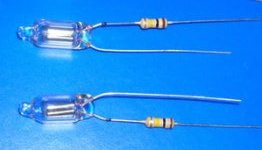
Just to confirm, if your NE-2 look like this, then, you only need the relay. You can connect them directly to 120/220 VAC.

neon0.jpg
 
What is the resistor value? Also, just to be clear, 14 bulbs need 14 resistors.

Delivering AC to the bulbs so both elements glow means that there are 7 AC-type switches per display. These can be relays or solid state switches. For example, a normal-looking little opto-coupler is available with a TRIAC output device. Seven of these per digit won't be cheap, but the result will look better than a DC supply and a switching transistor rated for 200 V.

MOC3010

ak
Resistor value is 120k ohms
 
Besides the opto mentioned above, others have back-to-back MOSFETs internally for the same effect - an optically-isolated, high voltage, low current switch. The MOSFET part has definite advantages in the telecom world, but not in a circuit where the action threshold of the device (the neon bulb) is around 60 V. Compared to that, a 2 V drop across a TRIAC is nuttin. Don't know which type is cheaper.

Isolation (optical, relays, whatever) will run up the price tag for the project, but the alternative is *very* dangerous.

ak
 
Status
Not open for further replies.

New Articles From Microcontroller Tips

Back
Top