Electro Tech is an online community (with over 170,000 members) who enjoy talking about and building electronic circuits, projects and gadgets. To participate you need to register. Registration is free. Click here to register now.
Welcome to our site! Electro Tech is an online community (with over 170,000 members) who enjoy talking about and building electronic circuits, projects and gadgets. To participate you need to register. Registration is free. Click here to register now.
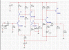
This is my circuit and I know that the first stage is a differential cascode amplifier, however I need someone to clarify my second stage amplifier with its name and functions. Thank you very much for your help
R11 and R12 in your circuit don't do anything and can be removed.
The load resistance should be much higher than R15. Add an emitter follower to drive a 100 ohm load.
Here is an article about two transistor circuits: **broken link removed** **broken link removed**
Your second stage circuit is similar to the CFP Complimentary Feedback Pair.
The second stage employs series-shunt feedback. So-called "current feedback" op amps use the same principle.
I agree with Audioguru about the emitter follower. Put it inside the feedback loop for best performance.
This site uses cookies to help personalise content, tailor your experience and to keep you logged in if you register.
By continuing to use this site, you are consenting to our use of cookies.