Continue to Site

Welcome to our site!

Electro Tech is an online community (with over 170,000 members) who enjoy talking about and building electronic circuits, projects and gadgets. To participate you need to register. Registration is free. Click here to register now.

  • Welcome to our site! Electro Tech is an online community (with over 170,000 members) who enjoy talking about and building electronic circuits, projects and gadgets. To participate you need to register. Registration is free. Click here to register now.

Need help to find element with mark IP5KF

hrischo192

New Member
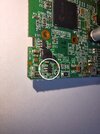
Hello, I have one broken reolink rlc-410 camera with broken element with marking on it IP5KF. I found one site where the element was IP5KJ and it maybe should be buck converter.
I need help to find same or alternative one to replace it. Iahve upload photos on board and element.
Thank you in the advanced.
20240608_130855.jpg
20240608_130921.jpg
20240608_131032.jpg
20240608_131045.jpg
 
I forgot to mark it, if it's not a problem I can paste link where I found same element but with j not with f
 

Attachments

  • 20240608_131056.jpg
    20240608_131056.jpg
    1.5 MB · Views: 34
Ahhh, silly me, I looked in the first picture. Incidentally, is the second picture a completely different board to the first picture?

Maybe a list of what the pictures are would help.

Mike.
 
I can't find any cross reference to the IP5xx part marking, but that is not unusual for surface mount part codes.

Aliexpress have some IP5 six pin ICs listed, but there is no way of knowing for certain that they are the same part. The part numbers listed against them come up as an eight pin device or a six pin LED driver...

(The last two digits are probably coding for the manufacturing date or site, so vary batch to batch.)

 
Photos are on mainboard of the camera, front side and bottom side. The broken element was soldered on front side of the board and traces went to 4pin white connector on bottom side. That 4pin connector is to connect other board with infrared and one sensor on it. The idea is when the night come to turn on infrared for night mode.
How I understand that this element is broken, so when it was soldered and infrared board is connected when hide sensor the camera have relay that should click and turn the night mode but it's not worked. After removed IP5KF the camera relay begin to clicking with shade on sensor but infrared leds and turn on. So, that element is to power on the infrared leds when the night comes.
The camera connector on motherboard is the fled plug and for infrared board is that 4pin white connector. And I used reolink mobile app to see what's happened.
Also I test infrared board to power it on with power supply and leds light up at 8v consumption is 0.020a and the leds are not broken. I think the buck converter should be with input 12v and output 8v, but I am not sure.
20240610_105551.jpg
20240610_105619.jpg


That's the link where I found that it's maybe a buck converter.
LinkScreenshot_20240610_110206_Chrome.jpg
 
I can't find any cross reference to the IP5xx part marking, but that is not unusual for surface mount part codes.

Aliexpress have some IP5 six pin ICs listed, but there is no way of knowing for certain that they are the same part. The part numbers listed against them come up as an eight pin device or a six pin LED driver...

(The last two digits are probably coding for the manufacturing date or site, so vary batch to batch.)

Thank you for your answer. That look very good. I contact with my friend and he told me that it's buck converter or led driver. But in my previous post I added link and screenshot where the element is with one different digit and say buck converter and I am confused.
 
OK, if it's the LED driver, the aliexpress ref may be correct and it's an MP2370 or clone of that?

Datasheet link in this:

I also think may be it's correct one because after check pins using datasheet looks good. Main possitive trace went to pin 5, main negative went to pin2 also between pin1 and pin6 I have capacitor as should be. So I will make order and I will try. Thank you very much. After receive it and replace it I will say what's happened.
 
There are literally, hundreds of similar parts in the same SOT23-6 package, all "Simple switchers" acting as step-down regulators. The variables include switching frequency range, in/output current/voltage range. These may affect optimal component values.

It would take more estimates of in/out values to compare specs to find a better match but if it still works, OK good luck.

1718024570151.png
Ref

1718031128670.png


Last edited:
IR LEDs in a 2-SMD or PLCC2 case are typically 1.35V @ 50 mA or 1.6V @ 100 mA
If the 18 LEDs are wired 6S3P that would translate to 8.1V @ 150 mA or 9.6V @ 300 mA

This is just an initial guess.

If it uses a typical Vref of 150 mV then the R750 current sensor implies Iout = 150/750= 200 mA
 
Last edited:
Thank you for reply. The schematic of the element should be on pin2 ground and pin5 possitive. Also between pin 1 and pin 6 I have capacitor and looks like pins description on mp2370 datasheet. I powered all infrared leds with 8V and 0.100A and consumption was 0.020A
Screenshot_20240610_214312_Samsung Notes.jpg
 
20 mA at 8V is on the low end but normal. Since the Sense Voltage=0.15V and the sense power resistor is R750.
The LEDs need 200 mA for the regulator to work, which may rise to 9. This means any of those simple regulator IC's may work from my previous posts. The pin labels may change but mean the same as shown in https://www.electro-tech-online.com...d-element-with-mark-ip5kf.166225/post-1452576
Thank you for the explanation. I have not yet ordered a driver for led mp2370. Am I to understand that it won't work for me?
 

Latest threads

Back
Top