Hi Guys,
I'm a newbie in this area and have a project for which I need to make an 200 Vac signal(f=100Hz) from a 3.7Vdc input signal.
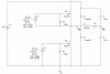
As you all can see in the attached figure, a "flyback converter" has been used in the first-stage to boost the 3.7 VDC to 200 VDC and then a half-bridge scheme in the second stage to produce an arbitrary unipolar output and also recovering charge from the load.
The 22 nf Can you tell me how I can figure out the value for L?
My capacitors at the output are both 22nF capacitors are representing my load so I cannot change them.
I have problem in driving the mosfet switches in case of Ql and Qh. In fact I'm trying to simulate the 2nd stage in Pspice which you can see in the second figure. Can you please help me driving my Mosfets? also I cannot get a 100hz 200 VAC output signal. How can I calculate the L in this circuit?
**broken link removed**
**broken link removed**
I'm a newbie in this area and have a project for which I need to make an 200 Vac signal(f=100Hz) from a 3.7Vdc input signal.
As you all can see in the attached figure, a "flyback converter" has been used in the first-stage to boost the 3.7 VDC to 200 VDC and then a half-bridge scheme in the second stage to produce an arbitrary unipolar output and also recovering charge from the load.
The 22 nf Can you tell me how I can figure out the value for L?
My capacitors at the output are both 22nF capacitors are representing my load so I cannot change them.
I have problem in driving the mosfet switches in case of Ql and Qh. In fact I'm trying to simulate the 2nd stage in Pspice which you can see in the second figure. Can you please help me driving my Mosfets? also I cannot get a 100hz 200 VAC output signal. How can I calculate the L in this circuit?
**broken link removed**
**broken link removed**
Attachments
Last edited:
