Continue to Site

Welcome to our site!

Electro Tech is an online community (with over 170,000 members) who enjoy talking about and building electronic circuits, projects and gadgets. To participate you need to register. Registration is free. Click here to register now.

  • Welcome to our site! Electro Tech is an online community (with over 170,000 members) who enjoy talking about and building electronic circuits, projects and gadgets. To participate you need to register. Registration is free. Click here to register now.

Need help with NE555P

Status
Not open for further replies.

Boomer

New Member
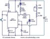
Okay so I built the circuit to the exact specifications for the 10 minute timer but I am having trouble getting it to work properly. Now I am fairly good with tracing a board but I have never built one from scratch till now and I would like to get this to work. Here is my issue I hook up the 9v battery and the LED turns on when I hit reset it goes out but the other LED does not show that it is in timing mode unless I swap the LED's leg, but when I put the LED to normally on it does not come back on after the timing process is over. How should I go about getting this to work? Also I would like to make it ground another momentary switch and automaticly reset.

Here is the schematic I used.
Thanks in advance
Boomer
 

Attachments

  • 10-minute_-timer-circuit.JPG
    10-minute_-timer-circuit.JPG
    29.9 KB · Views: 886
There should be no connection between pin 2 and pin 4. R1 should be connected between +9v and pin 2. Pin 4 should be connected to +9v.

Ken
 
After the Reset button is momentarily pushed, and then RELEASED, pin 3 of the Timer goes high for the timing period. When you initially connect the 9V battery, the timer comes up in the triggered state, just like you initiated a new timing cycle by pushing the button.

If it is the lower LED that is lit, and never goes out, this means the timer never completes its timing cycle. That could be caused by excessive leakage in the 150uF timing capacitor. If the current sourced through the ~2.5meg timing resistor is less than the leakage of the capacitor, the timing capacitor will never charge high enough to terminate the timing cycle.
 
please disreguard my post. I had a brain fart.
 
Last edited:
KMoffet: the circuit is fine as drawn.

K7ELP: the circuit is fine as drawn; if connected as you show, you will instantly vaporize one or both of the LEDs when you hook up the battery!

Stare at this sim of the posted circuit.
 

Attachments

  • Draft42.png
    Draft42.png
    39.8 KB · Views: 389
MikeMI,
Thanks for the correction. You are correct.
 
Status
Not open for further replies.

Latest threads

New Articles From Microcontroller Tips

Back
Top