electronicsfreak
Member
Well, here's my situation. Small hobby project that has found varying frequencies of noise winding it's way into the Micro's ADC. Sweet, looks like I've done a "fantastic" job at keeping everything clean 
Overall, I have a sensitive circuit feeding the ADC to a microcontroller. The micro also uses an LED matrix display through a driver....a very noisy LED display driver as I've now found, the Holtek HT16K33. Power is supplied to everything in a "star" route from 3 AAAs, but it looks like I'll need to go further that just that.
Checking my "4.5v" (note the quotes) I get this stuff the whole way across, regardless of where I probe on my rail.


Low and behold, the frequency of that stuff seems to line up to a T to the settings I have put the display driver in, matching the refresh and duty rate described in the datasheet. I am fairly positive I've done a wonderful job of overlooking the ESR of those AAAs, but I could be wrong.
Taking a 100uF electrolytic cap and tagging it...anywhere on that rail (to gnd), I get a reduction of that peak by ~15mV. Cool to see an effect, but far lower than I was hoping for.
Further investigation, ditching the batteries and powering the thing from an LM7805 across ~1ft of 20AWG wire, the result looks about the same as above. However, bread-boarding one, and tagging the circuit's power rail less than 2 inches from the LM7805 regulator (with same wire gauge), I get this fantastic result below.

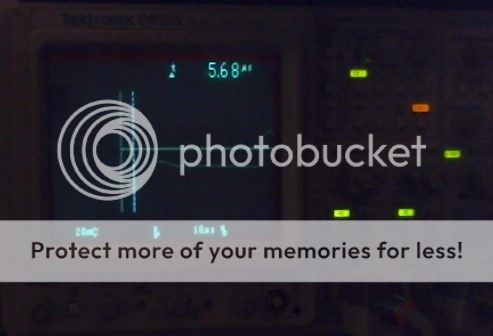
(apologies for the quality, only soo many hands when snapping the pic)
Again, I get the same looking scope result, regardless of where I probe on that rail.
Sweet, progress! Or, I think it is................that ~6uS edge looks a looot easier to clean.
Anyways, I am looking for opinion, or bits of advice of what I could try to keep that noise away from sensitive stuff on my circuit. I have a 100uF electrolytic at the center of the star, and 10uf, 1uF, and 0.1uF of ceramic bypass right next to the Holtek IC. Looking at adding a decoupling circuit (inductor/cap) to the feed of the Holtek IC, or....would it be better to put one on the power input of my sensitive stuff...or both? If I can't get away with just passives, I'm looking at adding a switching regulator, feeding a linear regulator. I would prefer to avoid it if possible, but I know that could mean adding an absurd amount of bypass?
As stated, just looking for any opinions, suggestions, tips, etc.
Thanks in advance for the input!
-EF
Overall, I have a sensitive circuit feeding the ADC to a microcontroller. The micro also uses an LED matrix display through a driver....a very noisy LED display driver as I've now found, the Holtek HT16K33. Power is supplied to everything in a "star" route from 3 AAAs, but it looks like I'll need to go further that just that.
Checking my "4.5v" (note the quotes
) I get this stuff the whole way across, regardless of where I probe on my rail.

Low and behold, the frequency of that stuff seems to line up to a T to the settings I have put the display driver in, matching the refresh and duty rate described in the datasheet. I am fairly positive I've done a wonderful job of overlooking the ESR of those AAAs, but I could be wrong.
Taking a 100uF electrolytic cap and tagging it...anywhere on that rail (to gnd), I get a reduction of that peak by ~15mV. Cool to see an effect, but far lower than I was hoping for.
Further investigation, ditching the batteries and powering the thing from an LM7805 across ~1ft of 20AWG wire, the result looks about the same as above. However, bread-boarding one, and tagging the circuit's power rail less than 2 inches from the LM7805 regulator (with same wire gauge), I get this fantastic result below.


(apologies for the quality, only soo many hands when snapping the pic)
Again, I get the same looking scope result, regardless of where I probe on that rail.
Sweet, progress! Or, I think it is................that ~6uS edge looks a looot easier to clean.
Anyways, I am looking for opinion, or bits of advice of what I could try to keep that noise away from sensitive stuff on my circuit. I have a 100uF electrolytic at the center of the star, and 10uf, 1uF, and 0.1uF of ceramic bypass right next to the Holtek IC. Looking at adding a decoupling circuit (inductor/cap) to the feed of the Holtek IC, or....would it be better to put one on the power input of my sensitive stuff...or both? If I can't get away with just passives, I'm looking at adding a switching regulator, feeding a linear regulator. I would prefer to avoid it if possible, but I know that could mean adding an absurd amount of bypass?
As stated, just looking for any opinions, suggestions, tips, etc.
Thanks in advance for the input!
-EF
