Continue to Site

Welcome to our site!

Electro Tech is an online community (with over 170,000 members) who enjoy talking about and building electronic circuits, projects and gadgets. To participate you need to register. Registration is free. Click here to register now.

  • Welcome to our site! Electro Tech is an online community (with over 170,000 members) who enjoy talking about and building electronic circuits, projects and gadgets. To participate you need to register. Registration is free. Click here to register now.

Noob here. Need advise on car electronics.

Status
Not open for further replies.

agentk98

New Member
Hi! I need your help on some things i would like to do in my car. I tried trying to calculate the stuff needed but got lost in the process. Here are my projects:

Project 1. DR Light / Blinker
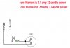
I installed a fender light on my car. I would like it to turn on with the Daytime Running Light (a little bit dimmed) but still function as a blinker (bright). I was suggested this schematic: (The left one)
**broken link removed**
The voltage source is the car alternator: 12v-14v
The load is a 12v/5w bulb

1. Is a 1N4001 Diode ok?
2. I initially used three 5w/10Ω ceramic resistors in series. They got too hot to touch. What would be a better one?


Project 2. LEDs
I have a couple of super bright blue LEDs that i got from an automotive store. They are supposedly plug and play. (no resistor) Though i'm sure a resistor will help prolong its life. The box had no information available as to its forward voltage, etc. What would be a good guess resistor value?

Thanks in advance!
Ken
 
there's ton of way to do what you want.. The most common solution wich doesn't need extra parts is:
one side of your lamp to the Parking wire, the other one to the Flasher wire. most car will acept this without problem.
 
Thanks, but would prefer to have them light in-sync. And they need to be dimmed as the socket can't stand the heat of being "always-on".
 
Ok then! so the solution you posted on the right side is the one to use... but i would add a diode in serie with the resistor to avoid, at least, all other parking lights to flash(even if dimmed) when you apply flasher.

Sure the resistors will comes hot really fast depending of how much you want to dim your lights. Use a power rate 2 times or more of the calculated value. OR use the solution i posted before but use higher voltage rated lamps... but you will miss a feature... nothing is perfect ;)

There's many solution so far.. it depend on how much complicated you want it.

For the LED solutions... if there's no documentation available... you could still use a variable DC source and play with the voltage until you reach a decent brightness. Once done, measure the voltage at the source output AND the current. Now you have everything to calculate the serie resistor.
 
Last edited:
If you can or will change your light socket you could use the dual filament bulbs the brake/signal lights use. One filament is for running lights and the other lights up much brighter for the brakes or signal.
The bulb and socket have 2 connections plus ground.
This marker location is usually not flashed but goes very bright for a turning light on higher end cars. Its very useful. It becomes a sidelight when signaling through a clear lens. If I had my choice I would light up where I'm turning rather than flash. Just my 20 milli-cents.:)

The LED shouldn't need any further resistance. You bought it in an autostore so it should be close already.
Something to consider whenever you put LEDS in a car is it isn't a 12 volt source but about 14.5V or so, your charging system.
My LED trailer lights I made (brother did the circuit) was kind of dim, until I started the car. Then the dimness made sense.
Try it with yours. Test it with the car off and then running.
 
what bulb are you using (type or number) here is a common bulb use in older american cars (1157) . here is my circuit idea.
 

Attachments

  • 11572.jpg
    11572.jpg
    71 KB · Views: 135
I appreciate the suggestions guys!

mister_e said:
Once done, measure the voltage at the source output AND the current. Now you have everything to calculate the serie resistor.
Thanks for this tip!

Techno said:
Something to consider whenever you put LEDS in a car is it isn't a 12 volt source but about 14.5V or so, your charging system.
Exactly. That's why i was wondering if i might burn the LEDs quickly as they are only rated at 12v. I guess a 1/4w/1k resitor will do?

I'm leaning on the left diagram as the diode would be much easier to stick back in the fender rather than the relay. So far i got 1n4001 diode and 10w/10Ω ceramic resistors. Will install them once i get the time.

I have no idea what bulb type or # this is. The automotive shop calls them peanut bulbs. They are small (half an inch length, quarter inch diameter) single filament. The dual-filament bulbs available are much bigger and wont fit. I wish they mnade them this small though. Would save me the hassle of all the components... :D
 
Status
Not open for further replies.

Latest threads

New Articles From Microcontroller Tips

Back
Top