Electro Tech is an online community (with over 170,000 members) who enjoy talking about and building electronic circuits, projects and gadgets. To participate you need to register. Registration is free. Click here to register now.
Welcome to our site! Electro Tech is an online community (with over 170,000 members) who enjoy talking about and building electronic circuits, projects and gadgets. To participate you need to register. Registration is free. Click here to register now.
The LED in the opto-coupler is turned on by R5 which turns on the opto-transistor so its collector is low. Then transistor Q1 is turned off causing its collector to be open.
R3 is in series with R6 which gives base current to Q2 that is turned on and its collector (the output) is low.
R4 causes feedback between Q1 and Q2 making them a Schmitt Trigger. Then they switch on and off very quickly with a "snap" action.
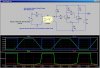
I redrew the circuit to show its true usefulness, namely to provide optically-isolated coupling where the input circuit does not have to be tied to the ground on the output circuit.
Note how the Schmitt Trigger squares up the slow edges of the input signal.
This site uses cookies to help personalise content, tailor your experience and to keep you logged in if you register.
By continuing to use this site, you are consenting to our use of cookies.