Continue to Site

Welcome to our site!

Electro Tech is an online community (with over 170,000 members) who enjoy talking about and building electronic circuits, projects and gadgets. To participate you need to register. Registration is free. Click here to register now.

  • Welcome to our site! Electro Tech is an online community (with over 170,000 members) who enjoy talking about and building electronic circuits, projects and gadgets. To participate you need to register. Registration is free. Click here to register now.

Optrex 323 1867 display

Status
Not open for further replies.

hotter

New Member
Hi, I would like to try to play with Optrex 323 1867 (rebranded as KYDE 3232351) monochrome display (256x26 pixels).
Bmw-Cd73-Optrex-Lcd-Glass-Professional-Radio-Cd.jpg


I did not find any documentation about it. The only thing I found is Optrex 323 display:
http://serdisplib.sourceforge.net/ser/optrex323.html

As I understand it contains of 2 displays, each has 34pins and contains 128x26 pixels. For start I would like to control one of them. I have the board from which display was taken. It has single 32pin connector to which all display and button data flow go.
fig-9.jpg


I have analyzed the board and identified which pins go through that connector:

Display pins -> (board connector) Meaning
Code:
2 -> (30) GND
3 -> (30) GND/Power +5V (One display goes to GND another to Power on this pin)
16 -> (30) GND
17 -> (26) Power +5V (with resistor 100 ohm)
18 -> ( 7) D0?
19 -> ( 8) D1?
20 -> ( 9) D2?
21 -> (10) D3?
22 -> (11) D4?
23 -> (12) D5?
24 -> (13) D6?
25 -> (14) D7?
26 -> (32)  ?  (with resistor 0 ohm)
27 -> (19)  ?  (with resistor 100 ohm and Capacitor to GND)
28 -> ( 5)  ?  (with resistor 100 ohm)
29 -> ( 6)  ?  (with resistor 100 ohm and Capacitor to GND)
30 -> (21)  ?  (with resistor 100 ohm and Capacitor to GND)

How could I identify these pins with "?" ? And how could I connect all these pins to Arduino?
 
Last edited:
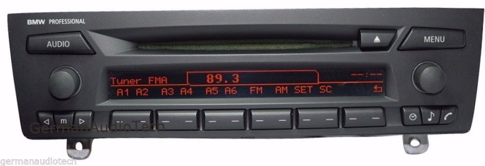
So I did further investigations. This display contains of 2 256x13 pixel displays.


Display pins -> Meaning (where goes on original board)
2 -> GND
3 -> GND/Power (one display goes to GND another to Power on this pin)
16 -> GND
17 -> Power
18 -> D0? (on original board goes to MC74VHC541 Bus Buffer chip pin Y8)
19 -> D1? (on original board goes to MC74VHC541 Bus Buffer chip pin Y7)
20 -> D2? (on original board goes to MC74VHC541 Bus Buffer chip pin Y6)
21 -> D3? (on original board goes to MC74VHC541 Bus Buffer chip pin Y5)
22 -> D4? (on original board goes to MC74VHC541 Bus Buffer chip pin Y4)
23 -> D5? (on original board goes to MC74VHC541 Bus Buffer chip pin Y3)
24 -> D6? (on original board goes to MC74VHC541 Bus Buffer chip pin Y2)
25 -> D7? (on original board goes to MC74VHC541 Bus Buffer chip pin Y1)
26 -> ? (on original board goes to MC74VHC541 Bus Buffer chip pin OE1)
27 -> ? (on original board goes to H8S/2674R microcomputer pin 89 PF4/HWR)
28 -> ? (on original board goes to H8S/2674R microcomputer pin 6 PC0/A0)
29 -> ? (on original board goes to H8S/2674R microcomputer pin 86 PF1/UCAS/IRQ14)
30 -> Power


What does MC74VHC541OE1 pin OE1 do? Also what do H8S/2674R pins PF4/HWR, PC0/A0, PF1/UCAS/IRQ14 do?
Any help on driving this display with arduino?
 
Thanks for reply. Any ideas how to debug this display further?
Is it possible to guess which drivers it uses?

Any insights would be useful, thanks.
 
Thanks for reply. Any ideas how to debug this display further?
Is it possible to guess which drivers it uses?

Any insights would be useful, thanks.

Sure, it is possible to guess, but that will likely not end well in my view.

I don't know what to tell you and a lot depends on your level of experience. You can start to get a picture of what is going on with Y1-Y8 being data and the OE line enabling the data to the controller. The others as control of some sort, but without a data sheet and code and without any specs at all, you are up against a real challenge.

Your best bet, again, in my opinion, is to continue to search for information. Failing finding something substantial (and it should be out there somewhere), I would let this one go unless you have a lot of experience and have a lot of time to devote to the task.
 
Sure, it is possible to guess, but that will likely not end well in my view.
Well I don't mind burning the screen if that is your worry. I have few of them. Still I would prefer not a brute force approach, but better to burn screens while trying than just to move on to other project. But I don't know from where to start guessing?

Well I am not very experienced, I don't have oscilloscope, I am thinking to build one with Arduino and try to see what signals original board sends to display, but not sure if I will understand it and will it be useful?..

Sadly I did not find any documentation about this display...
 
More investigations:
I am able to change contrast from original device, but I don't observe any voltage drop in any of the power or other pins. Does this mean that contrast could be sent as a command not as a separate pin input?

As I don't have oscilloscope (I am considering to get it if it would help), I used simple voltage tester, while display was powered in original device:
PC0/A0 = 0 - 0.01V (fluctuates from - to)
PF1/UCAS/IRQ14 = 3.27V (seems to be same as display power)
PF4/HWR = 3.26 - 3.27V (fluctuates from - to)
OE1 = 0.71 - 0.74V (fluctuates from - to)

Also I have over viewed these display drivers:
KS0108 - seems to be 5V power and does not have contrast command.
**broken link removed** - possible to power 3.3V and has contrast command, also can drive second slave display - possible candidate?
S6B0724 - possible to power 3.3V and has contrast command, also can drive second slave display - possible candidate?
sed1335 - seems to be 3.5V-5V? power and does not have contrast command, also can drive second slave display.
SED1520 - seems to be 5V? power and does not have contrast command. Can drive second slave display though.
SED1530 - seems to be 3.3 (SED1531) -5V? and has contrast command, also can drive second slave display - possible candidate? (Optrex 323 display also uses this)

Any other I should look into? Any other thoughts?
 
I am going to stick with what I said previously, but I respect your perseverance.

I am looking at it, rightly or wrongly, along this model...

Driver --> Controller(s) --> Display

To me, the driver is software/firmware. In your case it may be the code in the Renasas MC.

1. What other ICs are on the board, what do they look like and what is written on them. Unless I have missed something, you have not identified a controller. Maybe the Renesas is working as the controller, I don't know, but "normally", I would expect to see a controller.

2. What is the product that this comes from? Search for it and any other numbers or inscriptions or identifying marks that you can find. Sometimes you may not find somthing in a search because you are not using the right terms.
 
I am going to stick with what I said previously, but I respect your perseverance.
Not sure how long my perseverance will last, but I hope that someone, if not me, would hack it. I would love to see that you could take any display from any product and reuse it in your project.

Driver --> Controller(s) --> Display

To me, the driver is software/firmware. In your case it may be the code in the Renasas MC.

1. What other ICs are on the board, what do they look like and what is written on them. Unless I have missed something, you have not identified a controller. Maybe the Renesas is working as the controller, I don't know, but "normally", I would expect to see a controller.
Display has "Chip-On-Glass (COG)" (those black spots at the bottom), so it has controller built in. There is no other chip names on it only (Optrex 323 1867)
Bmw-Cd73-Optrex-Lcd-Glass-Professional-Radio-Cd.jpg

So I believe "Renesas" is working as driver and display has controller built in. Not sure how MC74VHC541 Bus Buffer chip impacts this, but maybe its not that important?

2. What is the product that this comes from? Search for it and any other numbers or inscriptions or identifying marks that you can find. Sometimes you may not find somthing in a search because you are not using the right terms.
This product comes from car radio "BMW professional radio" (2006-2013 year). I think they intentionally do not publish documentation of product display, I dont think companies want that consumers would mess with their products?
 
I think that you have to identify that controller and get the data sheet. At a bare minimum, you have to get some source code that uses that controller.

All of the controllers that I have used (I don't know, maybe a half dozen or so) require initialization before you can start telling them to display stuff. If you can't initialize the controller, you are up against a whole lot of "guessing".

Keep looking, some of these motor-geeks have done some very impressive reverse engineering. Have you tried to buy the display - working that angle? It may not be that old. Does BMW typically use a certain kind of controller in their displays? Anything to give you a leg up on just guessing.

Even if you had working units and a lot of sophisticated equipment, I don't know how easy it would be to work it all out. Maybe not impossible, but...well, you know.

Again I'm torn between, yeah repurposing and the traditional art of hacking is cool, and for what you can buy for a few bucks that is much better. Still, I would love to see you make progress if you are so-inclined to keep going.
 
Some people suggested to get 16channel logic analyzer. I am considering buying it. What do you think?
I think it should be easy to understand how display works, or it still wont be that easy?

The reason I want to hack this specific display and not to buy any other from ebay is that I would keep it and just add aditional information on it. I will try to leave original functionality, and intercept what it displays with Arduino. At least thats the n goal...
 
Sorry for the question; could you show how the display looks in current usage?
 
Never used an analyzer but my brand new DSO at the moment, helped a lot to develope a driver for PS2 with my 18F micro. The same for a 1Wire driver. Freezing frames and saving in memory is a good thing.

I am not going to keep posting suggestions (It is you who would do the hard work) but, provided that no further info is made available, and that you can peek inside while it works I would try to catch the initialization sequence. The most info you get, the better.

Being 2 displays (not sure myself of that) try to peek at the sequence to initialize the 128x64 GLCD where 2 halves are used. Maybe you find a hint or similarity there. Used them too long ago.

I would also try to see how it behaves with similar components (the buttons seem ideal to find kind of a pattern and what it is different for each one). At the same time, maybe that happens once, at turn on, and does not change anymore, ??

Record everything.

Making suggestions, everyone looks clever. I am stopping here.

Will follow this with interest. Please post if you think is worth your valuable time (the sole asset in life that you cannot get back, no matter what).

Buena suerte.
 
Hello,

without knowing the speed/frequency of the display's interface, it is hard to recommend a logic analyzer. With frequencies of a few MHz, I made good experience with those cheap (less than 10$) "Salea logic 8 clones" together with Sigrok/Pulseview as software (https://sigrok.org/). Unfortunately they only have 8 channels, so that multiple "recordings" would be required. For an overview of low-cost analyzers, you can take a look here: https://sigrok.org/wiki/Supported_hardware#Logic_analyzers

hotter: can you tell me where you got those displays from? I am looking for one (or two) of them as replacement, but at the moment everything I found was quite costly (at least too much for the radio of my 12 year old car).

Best regards
marrtn
 
Status
Not open for further replies.
Back
Top