Hi experts
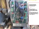
I'm a novice with electronics and was hoping someone here at an idea of how to fix this issue I am having with a 24V (battery powered - solar charged) gate motor control board. It seems to work more at night (so no power charging the batteries) and randomly during the day, unless it's hot/humid, then it just doesn't work.
I will post a pic of the unit and the board diagram from the manual if that helps.
The model is:
ISC800DC Sliding Gate Opener
So I have troubleshooted the following
Confirmed 26V volts at the board from the batteries.
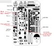
Confirmed the remote is working, by manually checking Relay 1 (opening the gate) works. I originally thought it was the relay not working, so I opened the top of Relay 1 (see pic) and manually actuated it while pressing the remote and the gate ran the Open Cycle. Without manually moving the contacts on the Relay, it doesn't run power to the motor. When the unit started playing up originally, a flick with the finger (tap) on the pcb outer cover while pressing the remote would get the gate to open.
Confirmed no power (obviously) on the PCB to the motor connector when the unit is playing up.
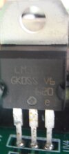
When the unit is playing up and not working with the remote, I have noticed this module (I believe it's a Voltage Limiter??) gets hot. I dont have an accurate temp on it, but it's almost too hot to touch.
I have installed switches to turn off solar charge to the batteries (so no power to the PWM controller from the solar panels but pwm still connected to batteries, so power available at the Load output of the PWM), and I have a switch to turn off power to the Control Board (which then allows that Module (voltage limiter) to cool down). Turning the power off to the PCB for a while, used to correct the problem until that unit heated up again. The manual shows the Load output of the PWM connects to the PCB of the gate motor.
I have checked the rear of the PCB and see no burn outs and have resoldered/cleaned the solder points on the pcb that looked dull.
If it's a simple fix, I would just rather replace a module on the PCB rather than buying an entirely new 24V electric gate, as it seems buying another complete kit is about the same price as a new control board and a lot of work to replace the entire unit. It's about 7 years old.
I think it's not getting the signal to engage the relays to run power to the motor somewhere, but as mentioned, manually actuating a relay while pressing the remote does send power to the motor, so I think the remote sensor on the pcb is working correctly. So whatever is supposed to actuate the relays (open and close) I think could be causing the issue. Could it be an internal failsafe on the PCB, for heat/outside temp/humidity? This model gate opener uses Magnets to determine if the gate is open or closed. All LEDS are lit when the unit is fully opened or closed, so I thought that meant the PCB was reading the gate position correctly?
Is that small blue box a relay as well? (see pic).
I'm totally stumped. I have to replace relay 1 as I have opened the top, and was thinking of replacing the other, plus the Blue Box one (if that's a relay also). It just doesnt make a lot of sense to me that it works fine for a few days and nights, then wont work sometimes, even at night.
Any help you experts could offer would be much appreciated.
I'm a novice with electronics and was hoping someone here at an idea of how to fix this issue I am having with a 24V (battery powered - solar charged) gate motor control board. It seems to work more at night (so no power charging the batteries) and randomly during the day, unless it's hot/humid, then it just doesn't work.
I will post a pic of the unit and the board diagram from the manual if that helps.
The model is:
ISC800DC Sliding Gate Opener
So I have troubleshooted the following
Confirmed 26V volts at the board from the batteries.
Confirmed the remote is working, by manually checking Relay 1 (opening the gate) works. I originally thought it was the relay not working, so I opened the top of Relay 1 (see pic) and manually actuated it while pressing the remote and the gate ran the Open Cycle. Without manually moving the contacts on the Relay, it doesn't run power to the motor. When the unit started playing up originally, a flick with the finger (tap) on the pcb outer cover while pressing the remote would get the gate to open.
Confirmed no power (obviously) on the PCB to the motor connector when the unit is playing up.
When the unit is playing up and not working with the remote, I have noticed this module (I believe it's a Voltage Limiter??) gets hot. I dont have an accurate temp on it, but it's almost too hot to touch.
I have installed switches to turn off solar charge to the batteries (so no power to the PWM controller from the solar panels but pwm still connected to batteries, so power available at the Load output of the PWM), and I have a switch to turn off power to the Control Board (which then allows that Module (voltage limiter) to cool down). Turning the power off to the PCB for a while, used to correct the problem until that unit heated up again. The manual shows the Load output of the PWM connects to the PCB of the gate motor.
I have checked the rear of the PCB and see no burn outs and have resoldered/cleaned the solder points on the pcb that looked dull.
If it's a simple fix, I would just rather replace a module on the PCB rather than buying an entirely new 24V electric gate, as it seems buying another complete kit is about the same price as a new control board and a lot of work to replace the entire unit. It's about 7 years old.
I think it's not getting the signal to engage the relays to run power to the motor somewhere, but as mentioned, manually actuating a relay while pressing the remote does send power to the motor, so I think the remote sensor on the pcb is working correctly. So whatever is supposed to actuate the relays (open and close) I think could be causing the issue. Could it be an internal failsafe on the PCB, for heat/outside temp/humidity? This model gate opener uses Magnets to determine if the gate is open or closed. All LEDS are lit when the unit is fully opened or closed, so I thought that meant the PCB was reading the gate position correctly?
Is that small blue box a relay as well? (see pic).
I'm totally stumped. I have to replace relay 1 as I have opened the top, and was thinking of replacing the other, plus the Blue Box one (if that's a relay also). It just doesnt make a lot of sense to me that it works fine for a few days and nights, then wont work sometimes, even at night.
Any help you experts could offer would be much appreciated.