Electro Tech is an online community (with over 170,000 members) who enjoy talking about and building electronic circuits, projects and gadgets. To participate you need to register. Registration is free. Click here to register now.
Welcome to our site! Electro Tech is an online community (with over 170,000 members) who enjoy talking about and building electronic circuits, projects and gadgets. To participate you need to register. Registration is free. Click here to register now.
How can people be expected to offer advise on a programmable chip, when we don't know if it's programmed correctly, or even what it's supposed to do, and you don't even mention what's wrong with it?.
I'm somewhat bemused by this? (and so are my secret team of comedy writers ) - but you haven't programmed the chip to do anything!, so what are you expecting it to do?.
If you buy a blank video tape, and put it in your VCR, do you expect to get a film from it? - NO - because it's blank, so why do you expect your blank PIC to do something?.
Maybe sitting and doing nothing is how it's supposed to work. You could keep applying voltage till the magic smoke comes out. Did you know all electronics works on magic smoke? If you release it, it will stop working.
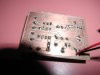
apparently they are the right resistors but round the wrong way or in the wrong order or something.....he didint specify.
Better start hitting the books in your school, someones pulling your leg; resistors are not polarized. Current can flow through them in either direction.
PS those red & black wires have to be between 2.5v & 5v else poof goes the PIC (hope it's not a 9v clip at the end)
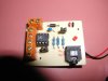
Ya know...a schematic is much more useful than photos of the circuit...easier to analyze.
What do you expect it to do anyways if you haven't programmed it for anything? Do you have a voltage regulator? How exactly are you trying to get 5V to the PIC?
What do you mean no voltage is running through it? The voltage measured across the +V and GND pin of the PIC is a floating voltage (constantly changing)? THat would mean there is a break between the traces going from the battery to the PIC. It's really hard to tell what you mean when you give so little detail and osbscure photos. No one is going to sit down and draw out the schematic themselves from your photos.
https://www.electro-tech-online.com/custompdfs/2006/07/axe090.pdf contains the circuit, this board is the PIC programmer and it only shows 2 resistors, 10K from serial in to ground and 22K to PIC pin2(ser in).. There is nothing to check, although I don't like using the sleeve of a 3 pin plug for data, that's where the shield (gnd) should be.
This site uses cookies to help personalise content, tailor your experience and to keep you logged in if you register.
By continuing to use this site, you are consenting to our use of cookies.

 ) - but you haven't programmed the chip to do anything!, so what are you expecting it to do?.