Continue to Site

Welcome to our site!

Electro Tech is an online community (with over 170,000 members) who enjoy talking about and building electronic circuits, projects and gadgets. To participate you need to register. Registration is free. Click here to register now.

  • Welcome to our site! Electro Tech is an online community (with over 170,000 members) who enjoy talking about and building electronic circuits, projects and gadgets. To participate you need to register. Registration is free. Click here to register now.

please Help!! @Microhydel power generation system for building roof rain water Project

Status
Not open for further replies.

remon7

Active Member
I have seen a video about electronic Project, now days I am trying to implement on my final year project. Practically I face with some trouble... for example. Real project they are getting 3+ volts/ampere from their project, but now I am getting 1.2volts, secondly how can I adjust everything’s. Like resistor, capacitor etc. on breadboard. Which things are important (parts/components) in this project? Focus: I want to turn on a light (6/9) volt battery. But my generated voltage is 1.2V. How can I increase these volts, I would like to turn on lights or charging battery (source). I would like to turn on my light or battery at the list. als I am planning to buy parts (transistor, resistor, capacitor etc.) today. So please tell me which things I have bought today, I have to finish this project by Friday. I have exam on it. also I need to write papers for it. Final Year project.
Real video:
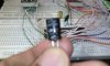
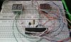
and about my project thats i am preparing :
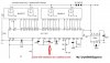
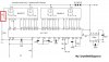
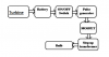
also this image: https://i.imgur.com/OG4Gcs7.png <<< Structure of my project.
please give me advices about this project. I will go to Electronic Shop for my project. So please give me list of parts, I will buy these this things tomorrow!!!
Hope everyone can give me your value advices about my Project.Waiting for you.Thanks for you in advance. Please known me. detail .
 
look this picture ... its mine project structure .
 

Attachments

  • circuit diagram.PNG
    circuit diagram.PNG
    33.2 KB · Views: 228
i would like to share with you about my project related a doc file. please tell me which components are important for my project, i will buy those parts. today.
 

Attachments

  • SEM-275. Green Wind Energy for rural electrification.doc
    239.5 KB · Views: 188
We don't do your projects/homework for you, although we can give guidance. Tell us what you have done so far towards the project, what you think you need to do next, and any particular part (besides only having 1-2V to work with) that you are having difficulty with.
 
There are many designs out there. Google 'DC-DC converter' or 'boost converter schematic'. That will give you a start.
 
i have read this article about boost up converter its quite perfect for my project. they discussed about 1.2volt to 5volt maybe it will work on my project or not. please reply me.
Its for
Step up dc converter 1.2v to +5v/-5v for micro computer
https://www.eleccircuit.com/step-up-dc-converter-1-2v-to-5v-5v-for-micro-computer/
Boost converter 5V to 12V
https://www.eleccircuit.com/boost-converter-5v-to-12v/ But its really impossible about generating 5volts from micro hydro electric project.

Thanks in advance for any input or recommendations ..
@alec_t
 
The first circuit you linked to looks as though it meets your needs. Simulation shows it should be able to provide ~ 15mA drive for a LED. Output voltage can be increased slightly by reducing the value of R2 and replacing the zener diode with e.g. a 5.6V one.
Don't forget to acknowledge the source of the schematic. Good luck with your exam.
 
now i am working on digital voltmeter too ... already i bought all components
Part's List:
1x - 220 Ohm Resistor
1x - 10K Resistor
1x - 15K Resistor
1x - 47K Resistor
1x - 100K Resistor
1x - 1M Resistor
1x 10K Pot
1x - 100pF Capacitor
1x - 10n Capacitor
1x - 100n Capacitor
1x - 220n Capacitor
1x - 470n Capacitor
2x - 10uF Capacitor
3x - 1N4148 Diode
1x - ICL7107 IC
1x - 7660 IC
2x - MAN6910 2-digit LED 7-segment Display
look this website https://projectlistinfo.blogspot.com/2013/01/how-to-make-digital-voltmeter.html
actually i am confused about its circuit setup can you help me about it ...
 
What about the setup do you find confusing?
 
i am working on it. its digital voltmeter. i bought all components. But i missed one capacitor..470nf ,,But i have 47uf ..is it similar. can i use it there ? Thanks
 

Attachments

  • 1554363_549898321789849_1924971640570304717_n.jpg
    1554363_549898321789849_1924971640570304717_n.jpg
    59.6 KB · Views: 206
  • 10308307_549898428456505_8749085979496261024_n.jpg
    10308307_549898428456505_8749085979496261024_n.jpg
    75.7 KB · Views: 199
  • AAAA.jpeg
    AAAA.jpeg
    86.5 KB · Views: 213
i missed one capacitor..470nf ,,But i have 47uf ..is it similar. can i use it there ?
No. It must be 470nF.
which pin is called DP ?
According to the schematic pins 4 and 9 are the decimal point connections. Check the datasheet for that display.
 
Status
Not open for further replies.

Latest threads

New Articles From Microcontroller Tips

Back
Top