Electro Tech is an online community (with over 170,000 members) who enjoy talking about and building electronic circuits, projects and gadgets. To participate you need to register. Registration is free. Click here to register now.
Welcome to our site! Electro Tech is an online community (with over 170,000 members) who enjoy talking about and building electronic circuits, projects and gadgets. To participate you need to register. Registration is free. Click here to register now.
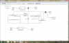
am modelling a buck converter with pwm on simulink ..but the circuit is not working am not getting much at the output ... i dought i have connected the the pwm right ....
am modelling a buck converter with pwm on simulink ..but the circuit is not working am not getting much at the output ... i dought i have connected the the pwm right ....
when i simulate it ..this is the error i get [At time 4.285525085934517e-005, simulation hits (1000) consecutive zero crossings. Consecutive zero crossings will slow down the simulation or cause the simulation to hang. To continue the simulation, you may.. Try using Adaptive zero-crossing detection algorithm
This site uses cookies to help personalise content, tailor your experience and to keep you logged in if you register.
By continuing to use this site, you are consenting to our use of cookies.

")