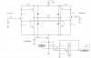
As you can see at the schematic, i placed a 0.1ohm sense resistor at the power supply negative rail. Furthermore, i used a differential opamp to amplify my voltage drop across my sense resistor to match my current flow across the sense resistor. From my simulation here, it might seem successful (except for a small percentage of error), but in practical i have to no idea wwhat will happen. Therefore, i just want to confirm and get the necessary confidence that this H-bridge with the current sensing will work.
Also, i added a transistor at the sense resistor for specifically for my PWM enable since im only limited to 1 PWM channel for 1 Hbridge driver.
Pls provide me with comments and opinions. THX THX THX :wink:
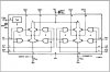
Also, i added a transistor at the sense resistor for specifically for my PWM enable since im only limited to 1 PWM channel for 1 Hbridge driver.
Pls provide me with comments and opinions. THX THX THX :wink: